Turbine of small-medium gas turbine and working method

A gas turbine and turbine technology, which is applied to gas turbine devices, machines/engines, mechanical equipment, etc., can solve the problem that the cooling structure of gas turbines is not suitable for small and medium gas turbine turbines, etc. The effect of high cooling efficiency

Inactive Publication Date: 2020-11-06
HARBIN ELECTRIC POWER GENERATION EQUIP NAT ENG RES CENT CO LTD
View PDF7 Cites 1 Cited by
  • Summary
  • Abstract
  • Description
  • Claims
  • Application Information

AI Technical Summary

Problems solved by technology

[0005] The research and development of the present invention solves the problem that the existing gas turbine cooling structure is not suitable for small and medium gas turbine turbines

Method used


Image

  • Turbine of small-medium gas turbine and working method
  • Turbine of small-medium gas turbine and working method
  • Turbine of small-medium gas turbine and working method

Examples


specific Embodiment approach 1

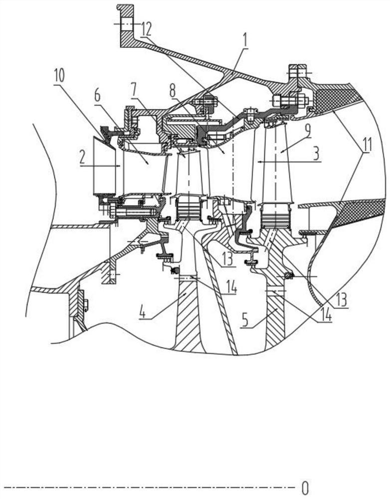
[0032] Specific implementation mode one: combine Figure 1-Figure 7 Describe this embodiment, the turbine of a kind of small and medium-sized gas turbine of this embodiment includes turbine cylinder 1, turbine inlet 2, turbine outlet 3, high-pressure turbine rotor 4, low-pressure turbine rotor 5, a static stage blade 6, first-stage moving blade 7, second-stage stationary vane 8, second-stage moving blade 9 and retaining ring 12, the two ends of the turbine cylinder block 1 respectively have a turbine inlet 2 and a turbine outlet 3, and the turbine cylinder The high-pressure turbine rotor 4 and the low-pressure turbine rotor 5 are arranged in sequence from the inlet side to the outlet side of the body 1, the outlet side of the turbine cylinder block 1 is connected with the retaining ring 12, the first-stage stator blade 6 is connected with the turbine cylinder block 1, and the first-stage dynamic The blade 7 is connected to the high-pressure turbine rotor 4 and drives the high-...

specific Embodiment approach 2

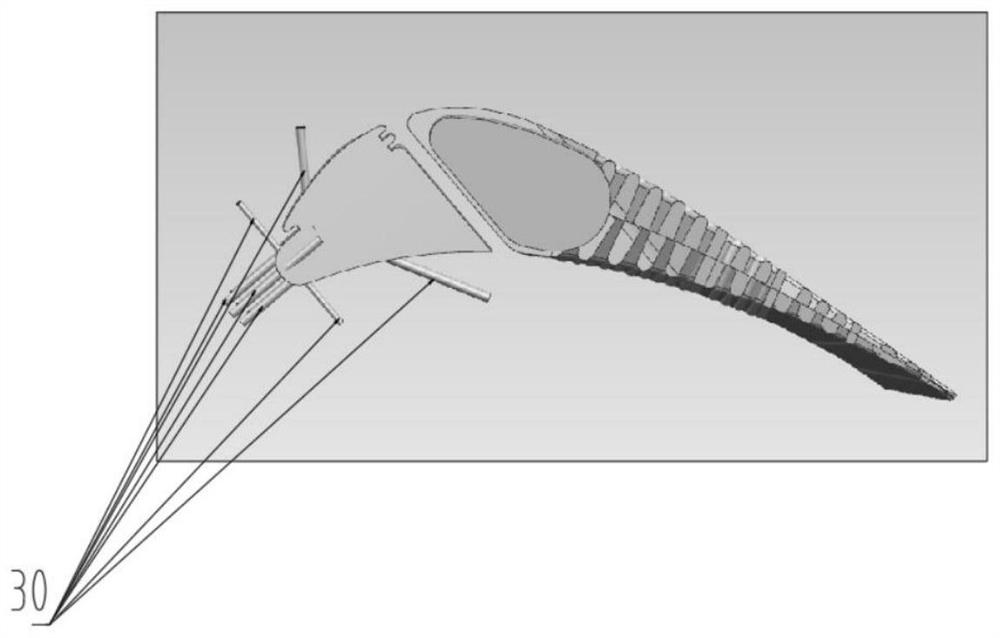
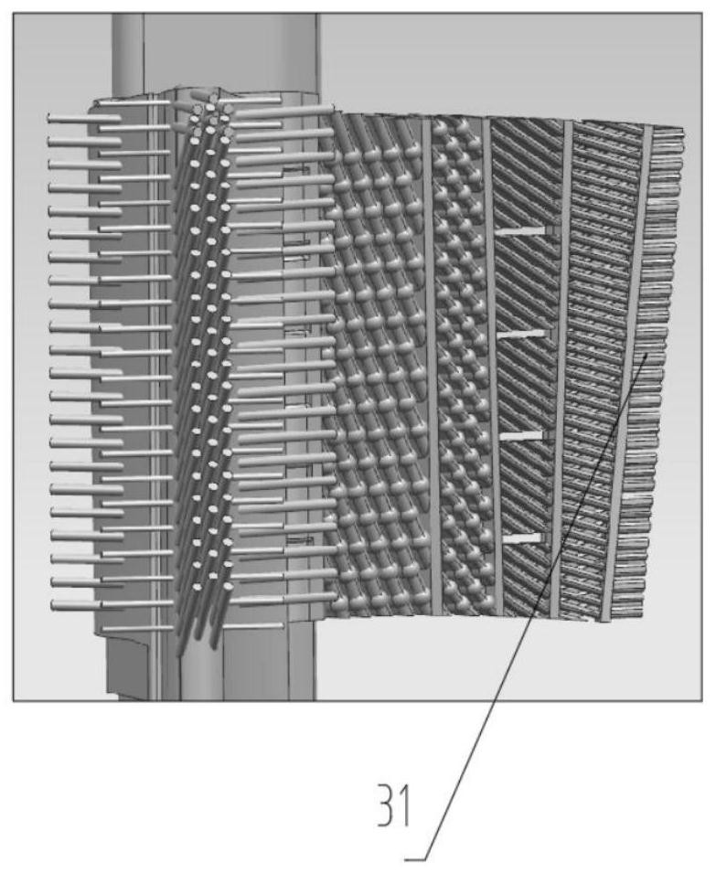
[0036] Specific implementation mode two: combination Figure 1-Figure 6 Describe this embodiment, a turbine of a small and medium-sized gas turbine in this embodiment, the first-stage stator blade 6 and the second-stage stator blade 8 both adopt a matrix rib structure, and the front edge of the first-stage stator blade 6 is provided with a film hole 30 ; Both the primary moving blade 7 and the secondary moving blade 9 adopt a matrix rib structure, and the matrix rib is a regular structure.

specific Embodiment approach 3

[0037] Specific implementation mode three: combination figure 1Describe this embodiment, a turbine of a small and medium gas turbine in this embodiment, the turbine cylinder 1 is provided with several cooling air passages along the axis O, and the cooling air passages are connected with the first-stage vane 6, the first-stage The internal passages of the rotor blade 7, the second-stage stator blade 8 and the second-stage rotor blade 9 and the gas channel are connected, and the low-temperature air flows into the interior of the first-stage stator blade 6 and the second-stage stator blade 8 through the cooling air channel on the cylinder block 1 channel, finally flows into the gas channel, and cools the components along the way.


PUM


Abstract

The invention relates to a turbine of a small-medium gas turbine and a working method, and belongs to the technical field of small-medium gas turbines and turbines of 20-30MW grade. The turbine of thesmall-medium gas turbine and the working method solve the problem that the prior cooling structure of a gas turbine is not suitable for a turbine of a small-medium gas turbine. The turbine comprisesa turbine cylinder body, a turbine inlet, a turbine outlet, a high-pressure turbine rotor, a low-pressure turbine rotor, a first stage stationary blade, a first stage movable blade, a second stage stationary blade, a second stage movable blade and a retaining ring. The turbine inlet and the turbine outlet are formed in both ends of the turbine cylinder body. The high-pressure turbine rotor and thelow-pressure turbine rotor are arranged successively from an inlet side to an outlet side of the turbine cylinder body. The outlet side of the turbine cylinder body is connected with the retaining ring. The first stage stationary blade is connected with the turbine cylinder body. The first stage movable blade is connected with the high-pressure turbine rotor. The second stage stationary blade isconnected with the retaining ring. The second stage movable blade is connected with the low-pressure turbine rotor. The aerodynamic efficiency at high speed is achieved by the two-stage rotors with different rotating speeds, and the blade stress is reduced. Matrix rib cooling structures are adopted by both the movable and stationary blades, and the cooling efficiency is high.

Description

technical field [0001] The invention relates to a gas turbine turbine and a working method, belonging to the technical field of 20-30MW small and medium gas turbine turbines. Background technique [0002] The gas turbine is an internal combustion power machine that uses continuous flowing gas as the working medium to drive the impeller to rotate at high speed, and converts the energy of the fuel into useful work. It is a rotating impeller heat engine. In the main process of air and gas, only the compressed air The gas turbine cycle composed of the three major components of engine, combustor and turbine is commonly referred to as a simple cycle, and most gas turbines adopt a simple cycle scheme. [0003] At present, for the gas turbine unit, an effective way to improve its cycle efficiency is to improve the aerodynamic efficiency and cooling efficiency of the turbine. The turbine stator vanes of heavy-duty gas turbines basically adopt the cooling structure combining impact an...

Claims


Application Information

Patent Timeline
Patent Type & Authority Applications(China)
IPC IPC(8): F02C3/04F01D5/18F01D9/02F01D25/12F01D11/02
CPCF01D5/186F01D9/02F01D11/02F01D25/12F02C3/04
Inventor 冯永志孙涛邵志伟姜东坡李翔宇单维佶葛春醒王颖苑馨予冀文慧
Owner HARBIN ELECTRIC POWER GENERATION EQUIP NAT ENG RES CENT CO LTD
Why Eureka
Try Eureka