
Bag pushing device

A technology of cam and fixed frame, applied in packaging and other directions, can solve the problems of low work efficiency and high production cost, and achieve the effect of continuous push, reduce production cost and improve work efficiency

Inactive Publication Date: 2019-02-19
CHANGZHOU INST OF MECHATRONIC TECH
View PDF0 Cites 0 Cited by
  • Summary
  • Abstract
  • Description
  • Claims
  • Application Information

AI Technical Summary

Problems solved by technology

The current manual push bag production method has low work efficiency and high production cost

Method used


Image

  • Bag pushing device
  • Bag pushing device
  • Bag pushing device

Examples


Embodiment Construction

[0013] The technical solutions in the embodiments of the present invention will be clearly and completely described below in conjunction with the drawings in the embodiments of the present invention.

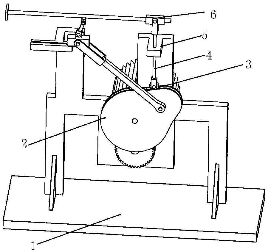
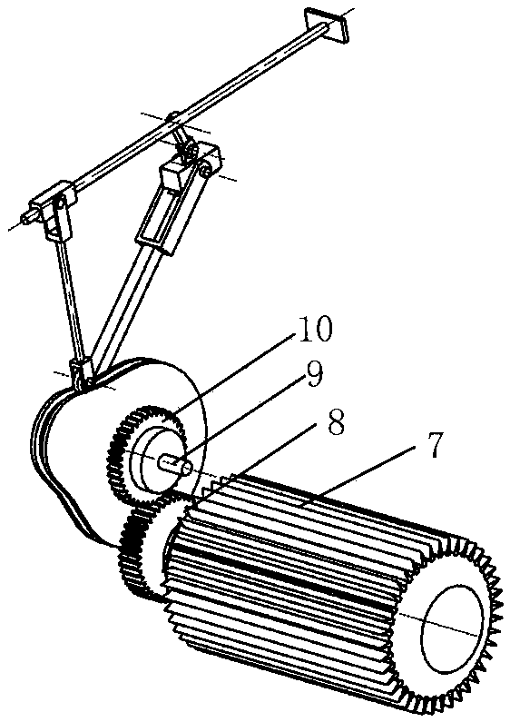
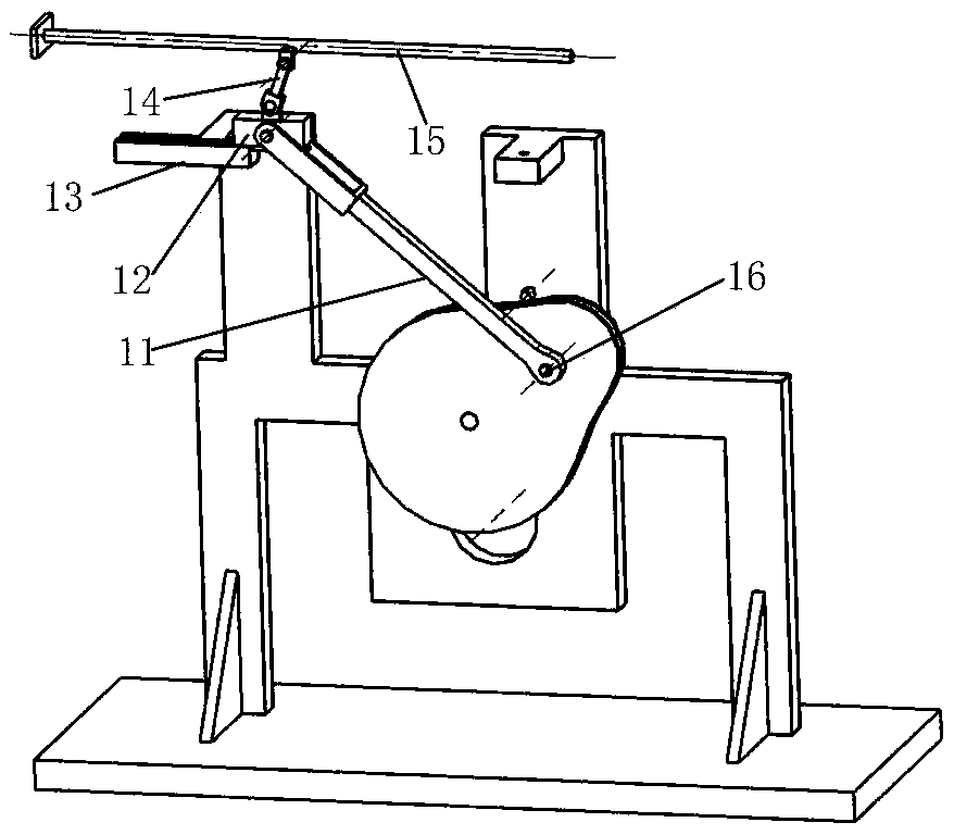
[0014] see Figure 1-3 Describe this embodiment, a bag pushing device, which includes a fixed frame 1, a transmission mechanism, a cam mechanism, a crank slider mechanism and a rocker slider mechanism, and the cam mechanism includes a cam 2, a roller 3, a roller shaft 4, Roller shaft groove 5 and cam shaft 9, described cam 2 rotation center is provided with cam shaft 9, and described transmission mechanism drives cam 2 to rotate around cam shaft 9, and described roller shaft groove 5 is fixedly connected with fixed frame 1, and described The roller shaft 4 is fixedly connected with the roller 3 after passing through the roller shaft groove 5, and the roller 3 moves along the outer contour of the cam 2, and the slider crank mechanism includes a connecting rod 11, a slider 12, a c...


PUM


Abstract

The invention provides a bag pushing device, and belongs to the technical field of packaging machinery, in particular to the bag pushing device. The problems of low working efficiency and high production cost of an existing manual bag pushing mode are solved. The bag pushing device comprises a fixed rack, a transmission mechanism, a cam mechanism, a slidercrank mechanism and a rocker sliding blockmechanism. The bag pushing device is mainly used for quickly and accurately sending products to specified positions of a packaging production line.

Description

technical field [0001] The invention belongs to the technical field of packaging machinery, in particular to a package pushing device. Background technique [0002] At present, in the field of packaging, the product needs to be transported to the designated position of the packaging line before packaging, and then packed by the packaging machine. How to quickly and accurately send the product to the designated position of the packaging production line and achieve continuous push is the key to improving packaging production efficiency. The essential. The current manual production method of pushing bags is low in work efficiency and high in production cost. Contents of the invention [0003] In order to solve the problems in the prior art, the present invention proposes a bag pushing device. [0004] In order to achieve the above object, the present invention adopts the following technical solutions: a bag pushing device, which includes a fixed frame, a transmission mechan...

Claims


Application Information

Patent Timeline
Patent Type & Authority Applications(China)
IPC IPC(8): B65B35/20B65B35/40
CPCB65B35/20B65B35/40
Inventor 白颖蒋庆斌王青莫莉萍
Owner CHANGZHOU INST OF MECHATRONIC TECH
Learn More