
Steel structure component transfer device

A transfer device and steel structure technology, applied in the direction of transportation and packaging, loading/unloading, conveyor objects, etc., can solve problems such as difficult stacking, disorderly arrangement, and easy downward collapse

Pending Publication Date: 2022-07-26
开封市黄河钢结构有限公司
View PDF7 Cites 0 Cited by
  • Summary
  • Abstract
  • Description
  • Claims
  • Application Information

AI Technical Summary

Problems solved by technology

[0003] However, with the current traditional transfer device, it is difficult to continuously push the steel structure components directly from the assembly line for transfer; the transfer of steel structure components relies on manual positioning and placement, which is time-consuming and labor-intensive, and it is difficult to automatically guide and place them in an orderly manner , and can be automatically reset; the steel structure components are stacked randomly, arranged out of order, easy to collapse downwards during the transfer process, and it is difficult to automatically stack them sequentially during placement; the steel structure components are stacked in sequence during the transfer process, and then Bundling with a binding device increases the stress on the rope, and at the same time, it is easy to cause deformation and damage to the finished product due to excessive force at the local binding position. It is difficult to place it by transferring the bracket to avoid the problem of excessive local stress.

Method used


Image

  • Steel structure component transfer device
  • Steel structure component transfer device
  • Steel structure component transfer device

Examples


Embodiment 1

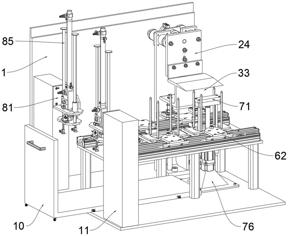
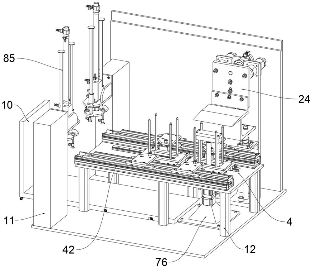
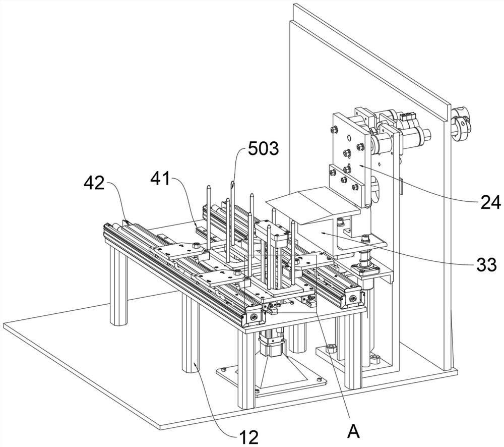
[0038] Please refer to Figure 1 to Figure 10 , this embodiment proposes a transfer device for steel structure components, including a main frame body 1, a bracket 5 and a sliding member 6; The left side of the top surface of the bottom plate of the main frame body 1 is fixed and vertically provided with two groups of uprights 11, the top surface of the bottom plate of the main frame body 1 is also provided with a support rod 12, and the top surface of the bottom plate of the main frame body 1 is also provided with a support rod 12. A supporting mechanism 7 is installed; a lifting device 8 is respectively installed on the right side of the opposite surfaces of the two groups of the uprights 11 ; an adsorption mechanism 9 is connected to the bottom of the lifting device 8 .

[0039] The top surface of the support rod 12 is connected with the transfer platform 4; the top surface of the transfer platform 4 is installed with a guide rail 41 and an electric slide rail 42;

[0040]...

Embodiment 2

[0052] On the basis of Example 1, the reverse flow setting operation can transfer the steel structural components on the transfer vehicle 10 to the next flow process line, that is, use the adsorption mechanism 9 to transfer the The steel structure components on the transfer vehicle 10 are lifted up to the transfer platform 4, so that the sliding member 6 is placed on the electric slide rail 42, and the bracket 5 is placed on the guide rail 41. The rail 42 and the sliding block 61 transfer the bracket 5 to the right side, and then use the supporting mechanism 7 to gradually lift the steel structure components on the bracket 5 upward. Use the push part 2 to push the steel structure components backward, pull the steel structure components back to the slope plate 3301, continue to push the steel structure components backward, and push them to the next assembly line to complete the transfer.

[0053] The specific usage and function of this embodiment: when the air pressure rod 22 i...


PUM


Abstract

The invention provides a steel structure component transfer device, and relates to the technical field of transfer devices. A pushing part is mounted on the right side of the front end surface of the main frame body back plate; a fixing plate is arranged on the front end surface of the pushing part; a guide frame is installed on the top face of the fixing plate, a fixing pipe is connected into the fixing plate, an air pressure rod is started to drive a pushing plate to move forwards and then drive a moving rod to slide forwards, the pushing plate synchronously drives the pushing plate to move forwards, and therefore a steel structure component to be transferred is pushed forwards; after a touch sensing piece on the front end face of a baffle makes contact with a circuit controller of a connecting frame which is touched and pressed to change an air pressure rod, the air pressure rod is folded to reversely drive a pushing plate to move backwards, so that reciprocating motion is conducted, continuous pushing of the steel structure component is achieved, subsequent transfer work is facilitated, and the working efficiency is improved. The problem that it is difficult to directly and continuously push the steel structure components from an assembly line so that the steel structure components can be conveniently transferred is solved.

Description

technical field [0001] The invention relates to the technical field of transfer devices, in particular to a transfer device for steel structural components. Background technique [0002] Steel structure is a structure composed of steel materials, which is one of the main types of building structures. Welds, bolts or rivets are usually used to connect each component or component. Because of its light weight and simple construction, it is widely used in large workshops, stadiums, super high-rises and other fields. Using the transfer device, the steel structure components are transferred to the next process or handled. [0003] However, with the current traditional transfer device, it is difficult to continuously push the steel structure components directly from the assembly line for transfer; the transfer of steel structure components relies on manual positioning and placement, which is time-consuming and labor-intensive, and it is difficult to automatically guide and place t...

Claims


Application Information

Patent Timeline
Patent Type & Authority Applications(China)
IPC IPC(8): B65G35/00B65G47/91B65G25/08B65G57/04B65G67/04
CPCB65G35/00B65G47/912B65G25/08B65G57/04B65G67/04
Inventor 孙卫东樊晨阳
Owner 开封市黄河钢结构有限公司
Learn More