Method, device and system for calibrating image pickup device

A technology of camera device and relative position relationship, which is applied in image analysis, image data processing, instruments, etc., can solve the problems of manpower consumption, high time cost, cumbersome manual calibration of camera device, etc., and achieve the effect of improving calibration efficiency.

Inactive Publication Date: 2019-02-19
北京爱笔科技有限公司
View PDF0 Cites 5 Cited by
  • Summary
  • Abstract
  • Description
  • Claims
  • Application Information

AI Technical Summary

Problems solved by technology

[0004] The existing camera calibration methods usually require manual operation, which not only consumes manpower, but also has a very high time cost.
When the scene area where the camera is deployed is very large and there are a large number of cameras deployed, it is obviously a very cumbersome task to rely on manpower to calibrate the camera

Method used


Image

  • Method, device and system for calibrating image pickup device
  • Method, device and system for calibrating image pickup device
  • Method, device and system for calibrating image pickup device

Examples


Embodiment 1

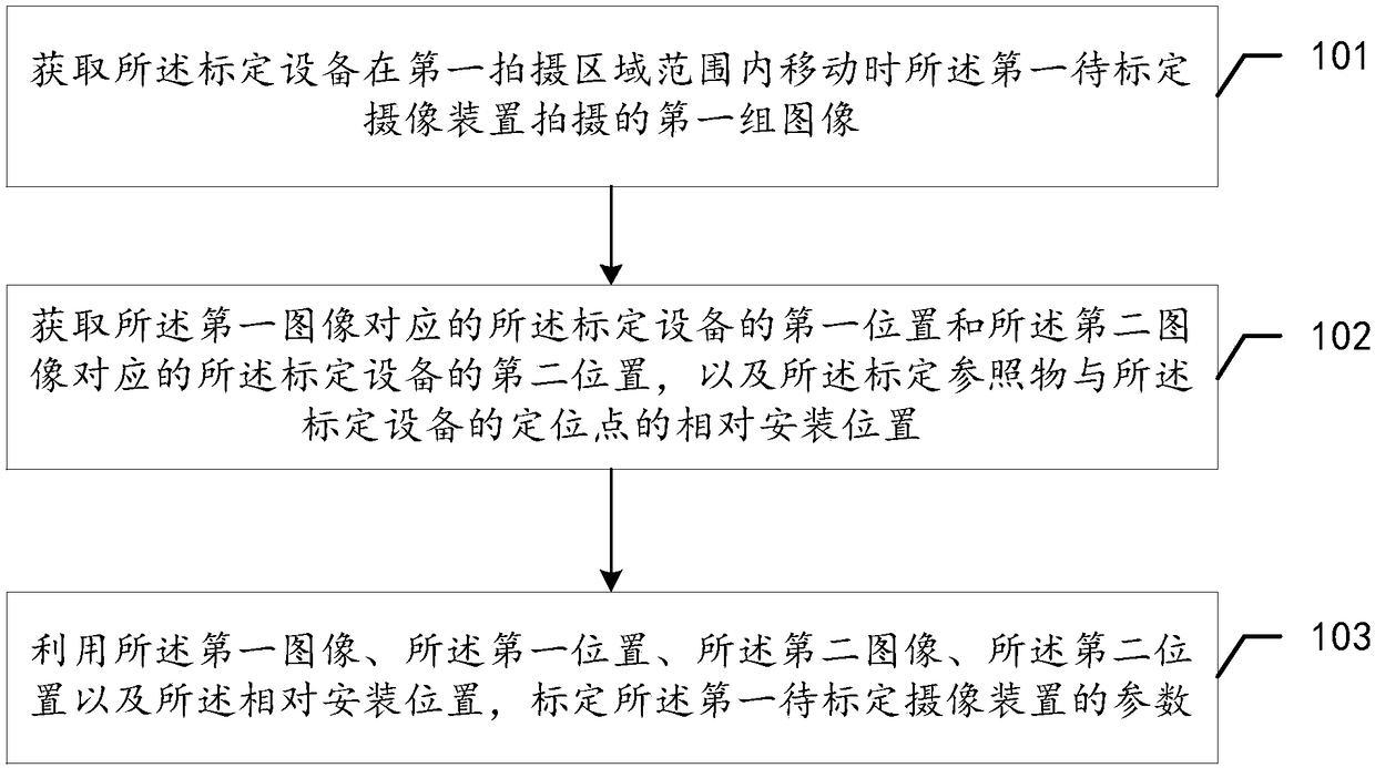
[0075] see figure 1 , which is a flow chart of a method for calibrating an imaging device provided in an embodiment of the present application.

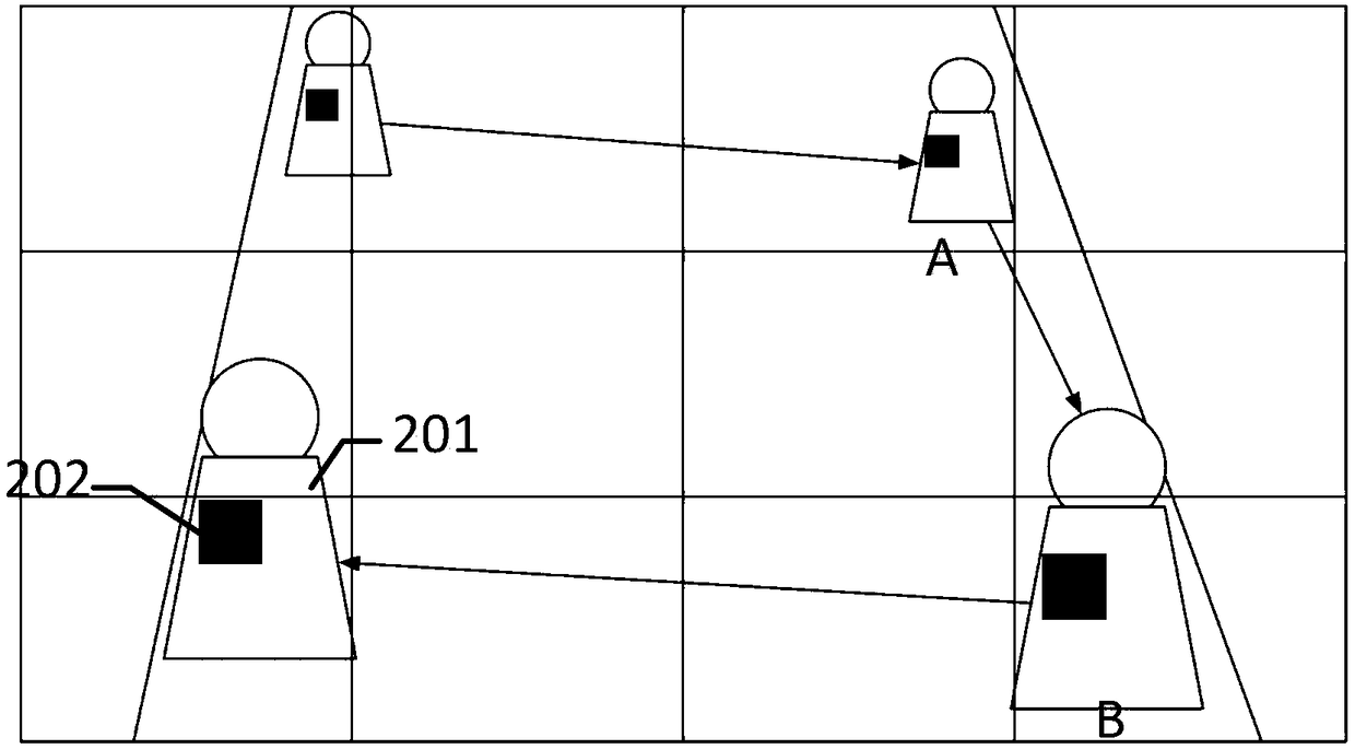
[0076] For ease of understanding, the application scenario of the method is firstly described below. At least one camera device to be calibrated is deployed in the scene, and each camera device to be calibrated can be calibrated according to the method provided in this embodiment. The method is applied to calibration equipment which is mobile during the calibration process. Specifically, the calibration device can move within the shooting area of ​​a camera to be calibrated, or move from the shooting area of ​​one camera to be calibrated to the shooting area of ​​another camera to be calibrated. As an example, the calibration device may be a robot.

[0077] It should be noted that, in this embodiment, a visible calibration reference object is installed on the calibration device. As an example, the calibration reference object may...

Embodiment 2

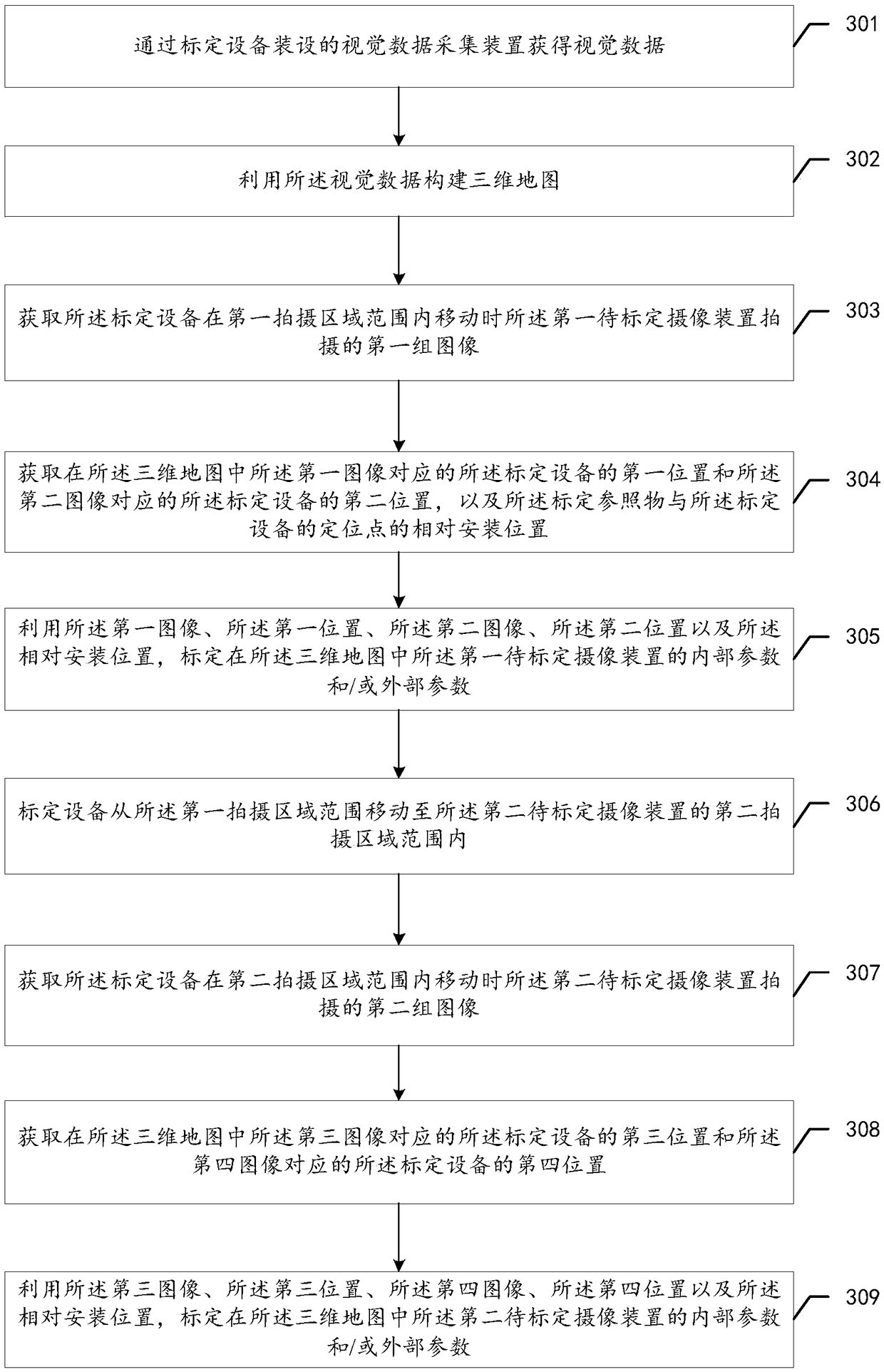
[0105] see image 3 , which is a flow chart of another method for calibrating an imaging device provided in an embodiment of the present application.

[0106] Such as image 3 As shown, the calibration method for the camera provided in this embodiment includes:

[0107] Step 301: Obtain visual data through the visual data acquisition device installed in the calibration equipment.

[0108] In this embodiment, the calibration device has a shooting function, and the shooting function is specifically realized by an installed visual data acquisition device. It should be noted that, in this embodiment, the function of the visual data acquisition device can be always turned on when the calibration device is moving in the scene. Therefore, the calibration device acquires visual data in the scene while moving.

[0109] In this embodiment, the visual data may be a scene picture or a scene video taken by the calibration device using a visual data collection device. The visual data a...


PUM


Abstract

The invention discloses a method, device and system for calibrating an image pickup device. The method is applied to a calibrate device, the calibration device is provided with a visual calibration reference object, The calibration device can move in the scene in which the camera device to be calibrated is deployed, the image collected by the camera device to be calibrated is acquired, the image is processed, the spatial position relationship between the calibration reference object and the camera device to be calibrated and self-positioning are established, and finally the method automatically and conveniently realize the calibration of the camera device to be calibrated in the scene. Compared with the prior art, the method does not need to perform calibration operation manually, and thecalibration efficiency of the image pickup device is remarkably improved.

Description

technical field [0001] The present application relates to the technical field of calibration of instruments and equipment, in particular to a calibration method, equipment and system for an imaging device. Background technique [0002] With the wide application of camera devices, at present, a large number of camera devices are used in many areas to monitor the area. Now there are some technologies to track moving targets in the scene by calling the images collected by the camera device deployed in the scene. [0003] Calibration of instruments and equipment is a routine method used in optical, electrical and mechanical fields to obtain accurate measurement results. In practical applications, if the parameters of the cameras deployed in the scene are not calibrated, the accuracy of the monitoring results obtained is poor. For example, it is difficult to link the motion trajectories of the same target object obtained by using the videos captured by two cameras deployed adja...

Claims


Application Information

Patent Timeline
Patent Type & Authority Applications(China)
IPC IPC(8): G06T7/80
CPCG06T7/80
Inventor 林根孙鑫
Owner 北京爱笔科技有限公司
Why Eureka
Try Eureka