Mold motion mechanism of bottle blowing machine

A technology of motion mechanism and bottle blowing machine, applied in the field of mold motion mechanism, can solve the problems of high control precision of rotary bottle blowing machine, affecting product quality, affecting mold clearance, etc., achieving high synchronization, reducing cost, and avoiding noise. Effect

Pending Publication Date: 2019-02-22
江苏辉河包装机械有限公司
View PDF5 Cites 0 Cited by
  • Summary
  • Abstract
  • Description
  • Claims
  • Application Information

AI Technical Summary

Problems solved by technology

[0006] The problem existing in the prior art is: the opening and closing of the mold on the left side and the mold on the right side, and the opening and closing of the bottom mold are controlled separately, and the relative movement of each guide rail and each bearing needs to be controlled very precisely so that the molds on both sides and the bottom mold can be moved simultaneously. The effect of mold opening and mold closing requires high control precision of the rotary blow molding machine. It is often difficult to precisely control the opening and closing of the left mold and the right mold, and the opening and closing of the bottom mold in the existing technology is always synchronized. Therefore, The left mold, the right mold, and the bottom mold are often loosely connected due to collisions, causing noise, affecting mold clearance, and affecting product quality

Method used


Image

  • Mold motion mechanism of bottle blowing machine
  • Mold motion mechanism of bottle blowing machine
  • Mold motion mechanism of bottle blowing machine

Examples


Embodiment Construction

[0024] The following will clearly and completely describe the technical solutions in the embodiments of the present invention with reference to the accompanying drawings in the embodiments of the present invention. Obviously, the described embodiments are only some, not all, embodiments of the present invention. Based on the embodiments of the present invention, all other embodiments obtained by persons of ordinary skill in the art without making creative efforts belong to the protection scope of the present invention.

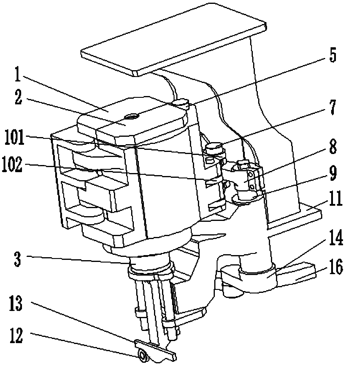
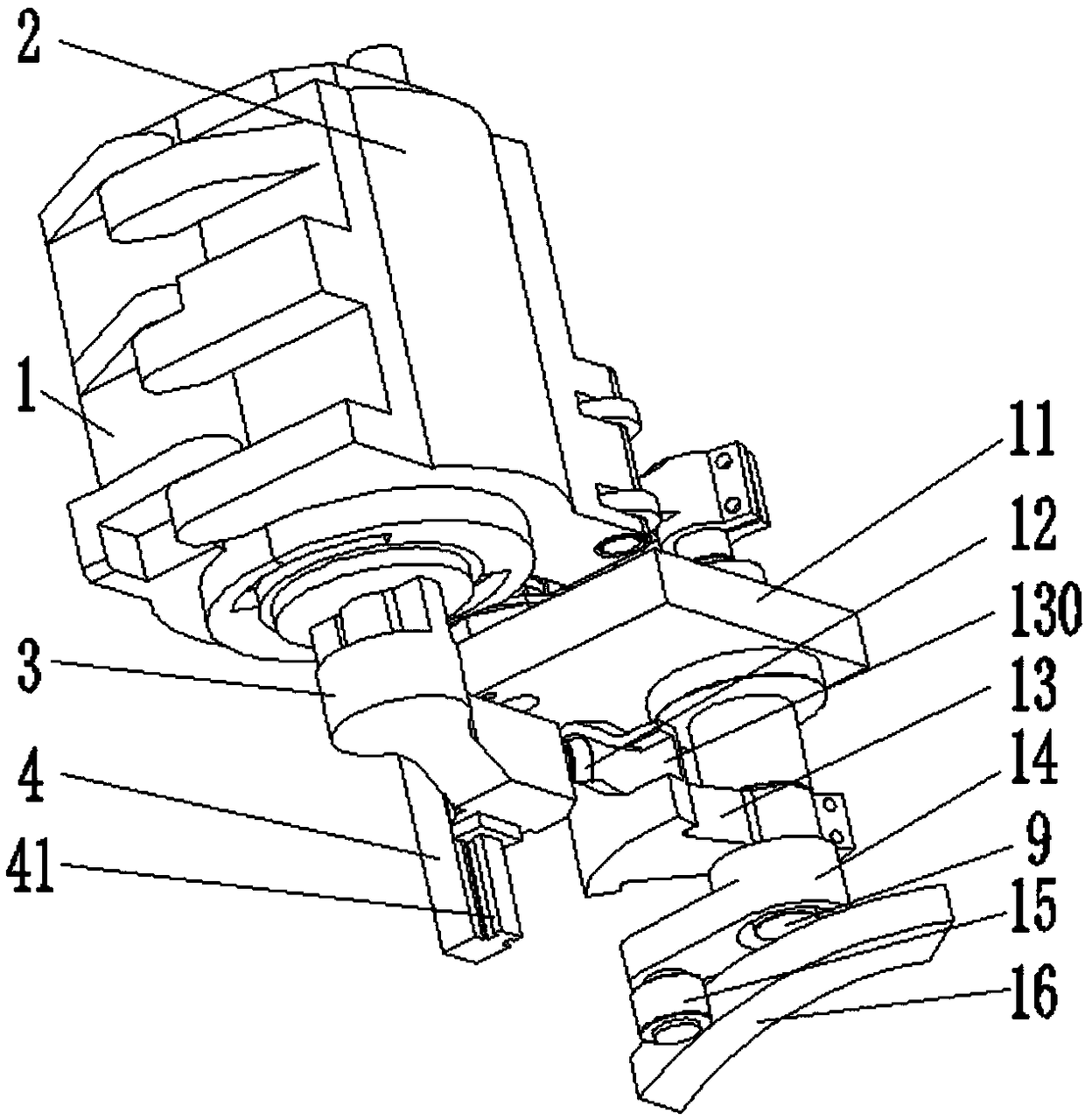
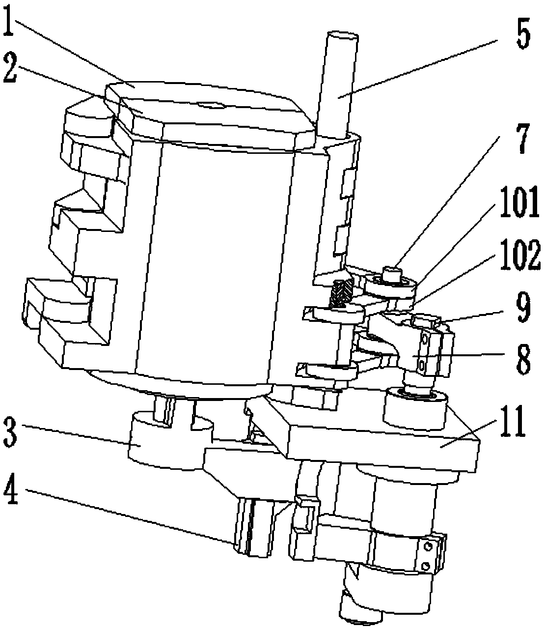
[0025] see Figure 2-5 , is an embodiment of the present invention, specifically:

[0026] A mold movement mechanism of a bottle blowing machine, comprising a left mold 1, a right mold 2, a bottom mold 3, a vertically arranged fourth connecting rod 9, a fixedly arranged frame 11, and a fixed and transversely arranged second guide rail 16. The fourth connecting rod 9 is rotatably connected to the frame 11. When the fourth connecting rod 9 rotates, the left mol...


PUM


Abstract

The invention discloses a mold motion mechanism of a bottle blowing machine. The mold motion mechanism comprises a left mold, a right mold, a bottom mold, a vertically arranged fourth connecting rod,a fixedly arranged rack and a fixedly and transversely arranged second guide rail. A fourth connecting rod and the rack are rotationally connected, and when the fourth connecting rod rotates, the leftmold and the right mold can be opened or closed. A first guide component and a third connecting block are further included. The rear end of the first guide component and the rear end of the third connecting block are fixedly connected with the fourth connecting rod, and the front portion of the third connecting block is in sliding connection with the second guide rail. The rear side of the bottommold and the first guide component are in sliding connection in the vertical direction and the left-right direction. The mold opening and closing actions of the left mold, the right mold and the bottom mold are synchronous. The precision requirement on mold opening and closing control is low, the structure can be simplified, and cost can be reduced.

Description

technical field [0001] The invention relates to the technical field of a fully automatic rotary bottle blowing machine, in particular to a mold movement mechanism of a bottle blowing machine. Background technique [0002] The rotary blow molding machine includes a frame, a first connecting rod vertically arranged above the frame and affixed to the frame, the inner side of the rear end surface of the left mold and the inner side of the rear end surface of the right mold are hinged through the first connecting rod, the left The outside of the rear end surface of the side mold and the outside of the rear end surface of the right mold are respectively hinged with a left second connecting block and a right second connecting block, and also includes a third connecting rod located behind the first connecting rod, a left second connecting block, The rear end of the second right connecting block is hinged by the third connecting rod; the front end of the first connecting rod, the sec...

Claims


Application Information

Patent Timeline
Patent Type & Authority Applications(China)
IPC IPC(8): B29C49/56
CPCB29C49/56
Inventor 蔡志义唐光海周志鹏徐忠
Owner 江苏辉河包装机械有限公司
Why Eureka
Try Eureka