
Blind area early-warning device installed on automobile rearview mirror

A technology of automobile rearview mirror and early warning device, which is applied in the direction of signal device, optical observation device, TV, etc., can solve the problems of unfavorable disassembly, waste, high cost, etc., and achieve the effect of simple structure

Inactive Publication Date: 2019-02-22
河南省全能科技有限公司
View PDF0 Cites 0 Cited by
  • Summary
  • Abstract
  • Description
  • Claims
  • Application Information

AI Technical Summary

Problems solved by technology

[0002] With the improvement of people's living standards, cars have gradually become people's means of transportation. Due to structural requirements, the car is designed with A, B, and C pillars. The A pillar is the pillar between the car windshield and the front door. , in the process of car driving, many accidents are caused by the A-pillar of the car blocking the driver's line of sight. The existing A-pillar blind zone warning device is designed as one with the rearview mirror, which is complicated to install and is not conducive to disassembly. Old cars install A The rearview mirror needs to be replaced together with the pillar blind spot warning device, which is costly and wasteful, so we need to design a new A-pillar blind spot warning device based on the car rearview mirror

Method used


Image

  • Blind area early-warning device installed on automobile rearview mirror
  • Blind area early-warning device installed on automobile rearview mirror
  • Blind area early-warning device installed on automobile rearview mirror

Examples


Embodiment Construction

[0014] In order to make the purpose, technical solutions and advantages of the embodiments of the present invention clearer, the technical solutions in the embodiments of the present invention will be clearly and completely described below in conjunction with the drawings in the embodiments of the present invention. Obviously, the described embodiments It is a part of embodiments of the present invention, but not all embodiments. Based on the embodiments of the present invention, all other embodiments obtained by persons of ordinary skill in the art without creative efforts fall within the protection scope of the present invention.

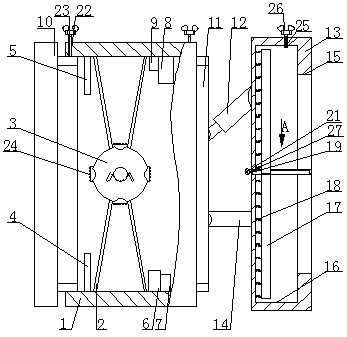
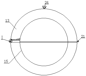
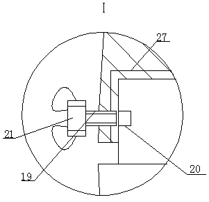
[0015]A blind spot early warning device installed in a car rearview mirror, as shown in the figure, includes a transparent internal thread cylinder 1, which is a transparent cylinder with internal threads inside, and the transparent internal thread cylinder The left side of 1 is open, and the right side is closed. The middle part of the inner circ...


PUM


Abstract

The invention relates to a blind area early-warning device installed on an automobile rearview mirror. The blind area early-warning device comprises a transparent internal thread cylinder, wherein theleft side of the transparent internal thread cylinder is open and the right side is closed. The middle part of the inner periphery of the transparent internal thread cylinder is fixedly connected with the outer ends of eight support rods uniformly distributed. The inner ends of the support rods are fixedly connected with the outer periphery of the same camera. An infrared sensor is fixedly mounted on the left part of the bottom side of the inner periphery of the transparent internal thread cylinder. An ultrasonic radar sensor is fixedly mounted on the left part of the top side of the inner periphery of the transparent internal thread cylinder. A storage battery is fixedly mounted on the right part of the bottom side of the inner periphery of the transparent internal thread cylinder. The device is simple in structure, can be directly arranged on the rear side of the automobile rearview mirror in a sleeving manner, can be directly and conveniently installed on the automobile rearview mirror without an early-warning device under the condition of not affecting the normal work of the rearview mirror and can be manually adjusted in monitoring angle according to different driving habitsand requirements of different drivers.

Description

technical field [0001] The invention belongs to the field of early warning devices, in particular to a blind spot early warning device installed in a car rearview mirror. Background technique [0002] With the improvement of people's living standards, cars have gradually become people's means of transportation. Due to structural requirements, the car is designed with A, B, and C pillars. The A pillar is the pillar between the car windshield and the front door. , in the process of car driving, many accidents are caused by the A-pillar of the car blocking the driver's line of sight. The existing A-pillar blind zone warning device is designed as one with the rearview mirror, which is complicated to install and is not conducive to disassembly. Old cars install A The rearview mirror needs to be replaced together with the pillar blind zone early warning device, which is costly and wasteful. Therefore, we need to design a new A-pillar blind zone early warning device based on the au...

Claims


Application Information

Patent Timeline
IPC IPC(8): B60Q9/00B60R1/12B60R16/02H04N7/18
CPCB60Q9/00B60R1/12B60R16/02H04N7/185
Inventor 王钰灵
Owner 河南省全能科技有限公司
Learn More