A stator structure with printed circuit board windings

A printed circuit board and stator structure technology, applied in the shape/style/structure of winding conductors, magnetic circuit shape/style/structure, structural connection, etc., can solve the problems of low interphase voltage of windings, limited use range, difficult to apply and so on , to achieve the effect of good heat dissipation, easy direct installation and large torque

Active Publication Date: 2017-05-31
QINGSHENG AUTOMATION TECH SHANGHAI
View PDF7 Cites 0 Cited by
  • Summary
  • Abstract
  • Description
  • Claims
  • Application Information

AI Technical Summary

Problems solved by technology

The Chinese patent with the application number CN200480009416.4 discloses a conductor-optimized axial field rotational energy device, which is mainly composed of a rotor and a stator. The radial conductor involved in the stator extends from the inner diameter through hole to the outer diameter through hole. Since the diameter of the through hole is much larger than the width of the radial conductor, the number of turns of each phase winding is small, the phase-to-phase voltage of the winding is low and the current is large under the same power, and it is difficult to apply to higher voltage occasions, which limits the scope of this patent. scope of use

Method used


Image

  • A stator structure with printed circuit board windings
  • A stator structure with printed circuit board windings
  • A stator structure with printed circuit board windings

Examples


Embodiment Construction

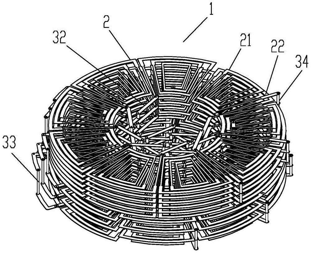
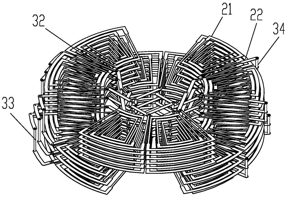
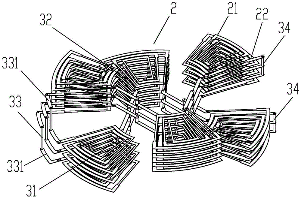
[0052] The structures, proportions, sizes, etc. shown in the accompanying drawings of the description are only used to match the content disclosed in the description, for those who are familiar with the technology to understand and read, and are not used to limit the conditions for the implementation of the present invention, so there is no Technically, any modification of structure, change of proportional relationship or adjustment of size shall still fall within the scope of the technical content disclosed in the present invention without affecting the functions and objectives of the present invention. within the range that can be covered. At the same time, terms such as "upper", "lower", "front", "rear", and "middle" quoted in this specification are only for the convenience of description, and are not used to limit the scope of the present invention. , the change or adjustment of its relative relationship, without substantive changes in the technical content, should also be...


PUM


Abstract

The invention provides a stator structure with printed circuit board windings, including a stator composed of at least three-phase windings, each winding includes a pair of winding units with the same structure, the winding units include upper and lower conductive layers, and the upper and lower conductive layers In the circumferential direction, a plurality of frame-shaped rotary coils corresponding to positions are respectively provided to form a rotary coil group. The frame-shaped rotary coil includes a plurality of alternately connected power guide rods and connecting guide rods. The two ends of the frame-shaped rotary coil are respectively The inner and outer connection ends, the two inner connection ends of the rotary coil group are connected in series through vertical conductive rods respectively, the two outer connection ends of adjacent rotary coil groups are connected in series through the first series conductive rod, and the upper and lower conductive ends of the winding unit The layers form a path, and the two outer connection ends of the two winding units are connected in series through the second series conductive bar. The invention has a disk-type flat structure, the radial dimension is larger than the axial length, light in weight, effectively increases the number of turns of the winding, and reduces resistance and eddy current loss.

Description

technical field [0001] The invention relates to a stator structure with printed circuit board windings. Background technique [0002] The stator is the stationary part of the motor and works in conjunction with the rotor. The stator is generally composed of three parts: the stator core, the stator winding and the frame. The main function of the stator is to generate a rotating magnetic field, while the main function of the rotor is to output torque. The Chinese patent with the application number CN200480009416.4 discloses a conductor-optimized axial field rotational energy device, which is mainly composed of a rotor and a stator. The radial conductor involved in the stator extends from the inner diameter through hole to the outer diameter through hole. Since the diameter of the through hole is much larger than the width of the radial conductor, the number of turns of each phase winding is small, the phase-to-phase voltage of the winding is low and the current is large unde...

Claims


Application Information

Patent Timeline
Patent Type & Authority Patents(China)
IPC IPC(8): H02K3/28H02K3/26H02K1/27H02K1/12
CPCH02K3/26H02K3/28H02K11/25H02K5/1732H02K1/182H02K1/2795
Inventor 易旭
Owner QINGSHENG AUTOMATION TECH SHANGHAI
Why Eureka
Try Eureka