Temperature drift trimming circuit for second-order curvature compensation reference source

A technology of trimming circuit and curvature compensation, applied in the field of compensation circuit, can solve the problems of high cost and difficult temperature drift adjustment, and achieve the effect of simplifying the trimming method, avoiding application limitations, and reducing the difficulty of layout design.

Pending Publication Date: 2019-02-22
58TH RES INST OF CETC
View PDF15 Cites 2 Cited by
  • Summary
  • Abstract
  • Description
  • Claims
  • Application Information

AI Technical Summary

Problems solved by technology

[0008] The purpose of the present invention is to provide a temperature drift adjustment circuit to solve the existing problem of high difficulty and high cost of temperature drift adjustment

Method used


Image

  • Temperature drift trimming circuit for second-order curvature compensation reference source
  • Temperature drift trimming circuit for second-order curvature compensation reference source
  • Temperature drift trimming circuit for second-order curvature compensation reference source

Examples


Embodiment 1

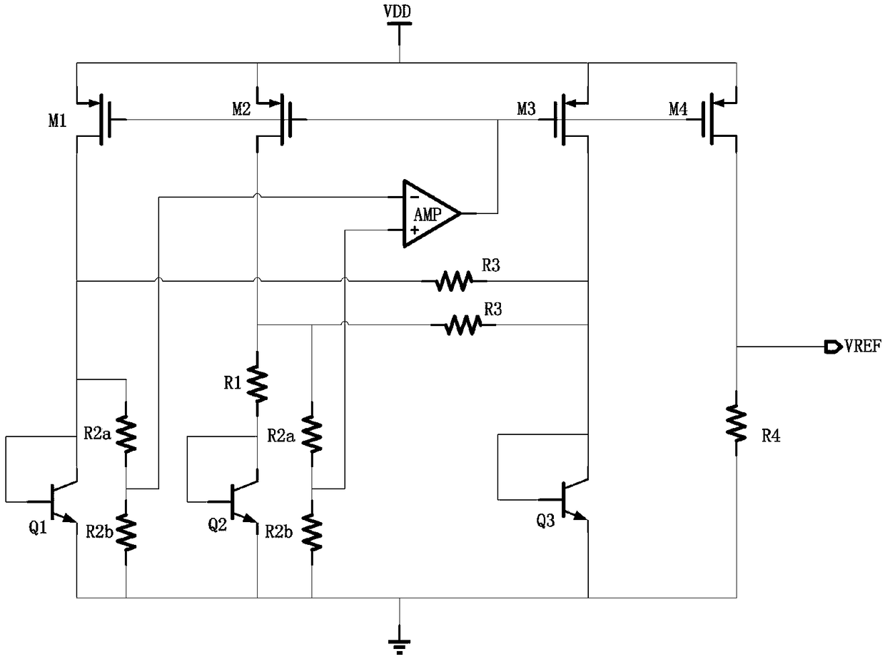
[0025] The structure of the existing second-order curvature compensation reference source is as follows: figure 1 As shown, it includes four PMOS transistors M1, M2, M3 and M4, three transistors Q1, Q2 and Q3, a resistor R1, two resistors R2a, two resistors R2b, two resistors R3 and an amplifier AMP.

[0026] Specifically, the gates of the four PMOS transistors are interconnected, and the sources are all connected to the power supply VDD. The collector of the transistor Q1 is connected to the drain of the PMOS transistor M1, the collector of the transistor Q2 is connected to the drain of the PMOS transistor M2, and the collector of the transistor Q3 is connected to the drain of the PMOS transistor M3; the three transistors Q1, Q2 The collectors of Q3 and Q3 are connected to their own bases; the emitters of the three transistors Q1, Q2 and Q3 are all grounded. One pair of resistors R2a and R2b are connected in series to the collector and emitter of the transistor Q1, respectiv...


PUM


Abstract

The invention discloses a temperature drift trimming circuit, and belongs to the technical field of compensation circuits. The temperature drift trimming circuit comprises a resistor R2a, a resistor R2b, a transistor Q4 and a transistor Q5; the resistor R2a and the resistor R2b are connected in series; a base electrode of the transistor Q4 is connected with a base electrode of the transistor Q5; after the resistor R2a and the resistor R2b are connected in series, the resistor R2a is connected to a collecting electrode of the transistor Q4, and the resistor R2b is connected to an emitting electrode of the transistor Q4. The temperature drift trimming circuit can achieve trimming only by using one set of resistors, the trimming mode is greatly simplified, and the application limitation caused by a resistor trimming matrix network is avoided; in the circuit layout design, only the matching design of the resistor R2a needs to be considered, and the layout design difficulty is reduced.

Description

technical field [0001] The invention relates to the technical field of compensation circuits, in particular to a temperature drift trimming circuit used for a second-order curvature compensation reference source. Background technique [0002] As the demand for power management products continues to grow, the requirements for power output accuracy continue to increase. A typical first-order bandgap reference can no longer meet the requirements of a large number of high-performance power systems, so a second-order corrected reference is required. [0003] At present, the second-order reference source circuit usually adopts the concept of curvature correction to compensate the nonlinear negative temperature coefficient of the diode. Its structure is as follows figure 1 shown. exist figure 1 Among them, transistor Q1, transistor Q2 and resistor R1 generate PTAT current component; transistor Q1, resistor R2a, resistor R2b and transistor Q2, resistor R1, resistor R2a, resistor ...

Claims


Application Information

Patent Timeline
Patent Type & Authority Applications(China)
IPC IPC(8): G05F1/567
CPCG05F1/567
Inventor 邱旻韡李娟陈红罗永波宣志斌肖培磊
Owner 58TH RES INST OF CETC
Why Eureka
Try Eureka