Staple gun

A nail gun and nail needle technology, applied in the field of nail guns, can solve problems such as failure to fire successfully, excessive elastic force, failure to complete the work purpose, etc., and achieve the effect of avoiding the situation of stuck nails

Inactive Publication Date: 2019-02-26
APEX MFG
View PDF6 Cites 0 Cited by
  • Summary
  • Abstract
  • Description
  • Claims
  • Application Information

AI Technical Summary

Problems solved by technology

[0003] However, although the general nail magazine has elastic parts to promote the tendency of the needles to move forward and replenish, the elastic force should not be too large to avoid poor needle ejection when firing the needles. There is not enough pushing force. When the striker touches the needle downwards, the lower end of the needle tends to move to the rear end of the nail box, causing the needle to be skewed. As long as the needle is slightly skewed, it may not be fired successfully, resulting in a The state of the staples will not only fail to complete the work purpose, but will also wear out the nail needle and the internal parts of the nail gun

Method used


Image

  • Staple gun
  • Staple gun
  • Staple gun

Examples


Embodiment Construction

[0029] The following examples only illustrate possible embodiments of the present invention, which are not intended to limit the protection scope of the present invention, and are stated in advance.

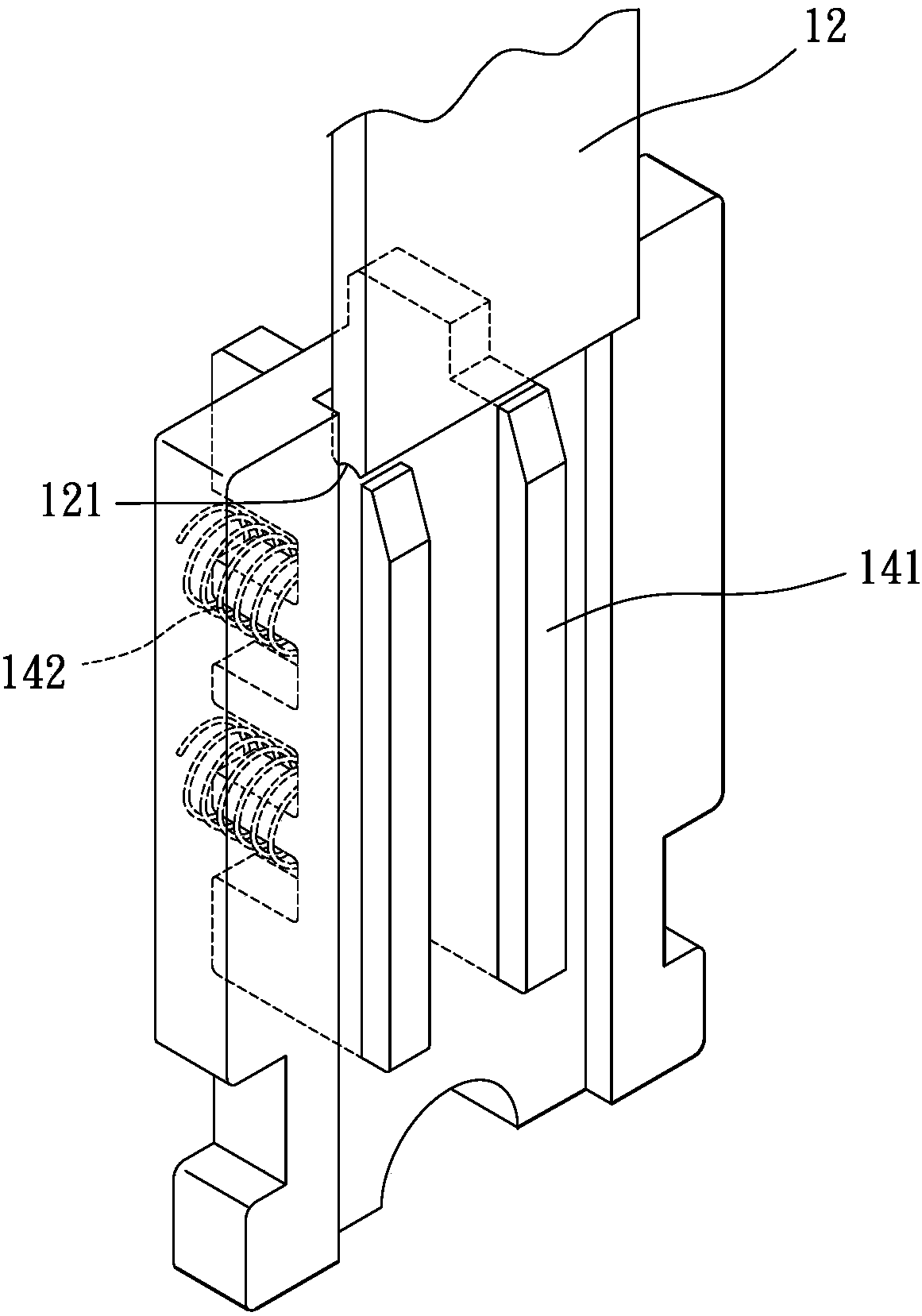
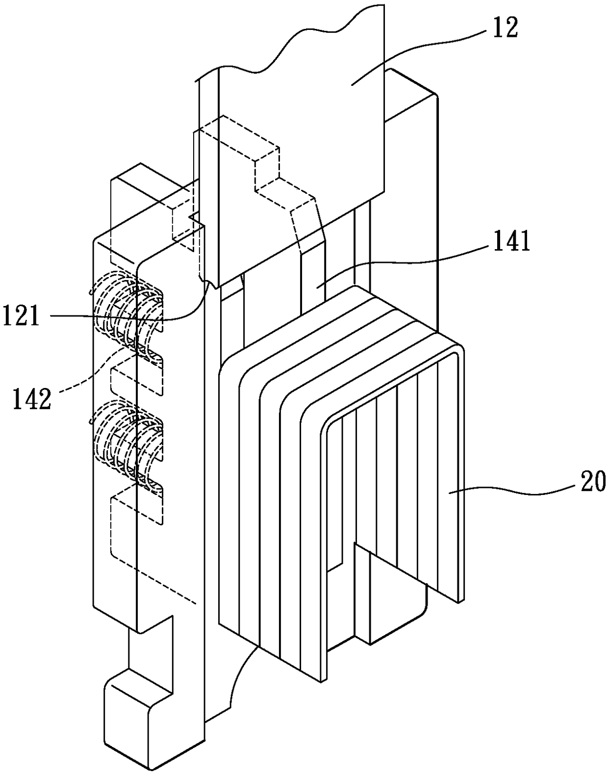
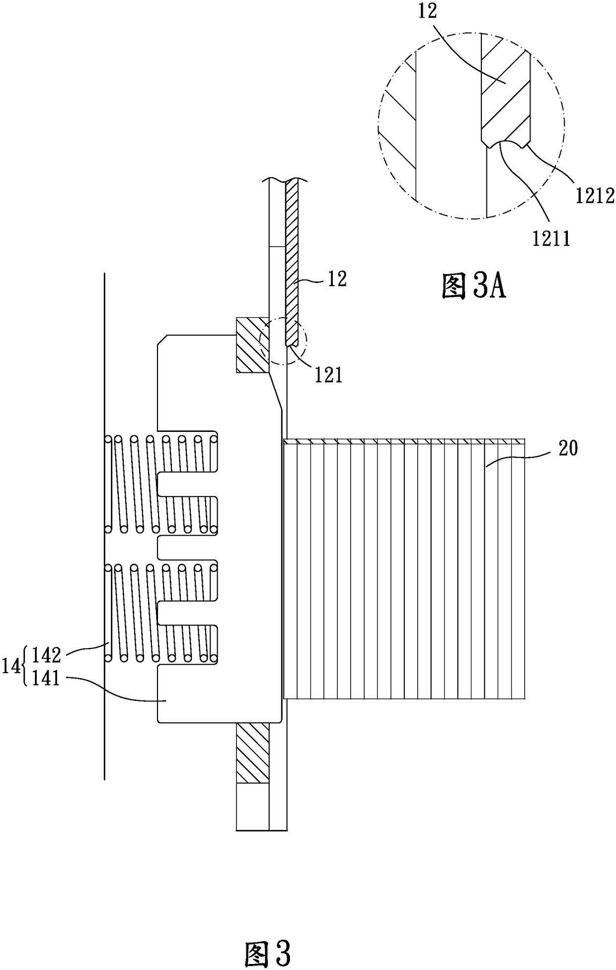
[0030] Please refer to Figure 1 to Figure 5 , The present invention provides a nail gun, comprising a body 10, a nail magazine 11, a striking plate 12, 12a, 12b and a driving part.

[0031] The main body 10 encloses an accommodating space and has an opening below its front end. The accommodating space communicates with the opening. The line connecting the front end and the rear end of the main body 10 defines a length direction; The needle 20 is accommodated; the striker 12, 12a, 12b is arranged on the front end of the body 10 and can slide vertically above the opening; the driving part is arranged on the body 10 and connected with the striker 12, 12a, 12b to drive the striker 12 , 12a, 12b move down to fire the nail needle 20. In this embodiment, the driving part includes a pr...


PUM


Abstract

The invention provides a staple gun. The staple gun comprises a body, a staple case, a striking plate and a driving part, wherein the body defines an accommodation space; an opening is arranged at thelower part of the front end of the body; the accommodation space communicates with the opening; the connecting line of the front end and the rear end of the body defines a length direction; the staple case is arranged in the body and accommodates a plurality of staples; the striking plate is arranged at the front end of the body and can slide above the opening of the body in a vertically linear manner; the driving part is arranged on the body and connected with the striking plate to drive the striking plate to move downward to shoot the staples; and the bottom end of the striking plate is ofa concave shape and comprises two convex opposite ends and a concave middle part. The staple gun provided by the invention can guarantee the staples to be upright and not be leaned, provides a uniformpush force to the staples, can avoid the staples from being stuck, can guarantee a staple to be really separated from a next staple, and avoids a plurality of staples or excess staples from being pushed out to cause the staples to be stuck.

Description

technical field [0001] The invention relates to a nail gun. Background technique [0002] The known nail gun has a body, a nail magazine, a striker and a driving part (usually a pressure handle, a trigger, etc.), the nail magazine is located in the body for accommodating nails, and the striker is arranged at the front end of the body. It can slide vertically and linearly, and the driving part is connected with the striking plate to drive it to move downward to fire the nail. [0003] However, although the general nail magazine has elastic parts to promote the tendency of the needles to move forward and replenish, the elastic force should not be too large to avoid poor needle ejection when firing the needles. However, this also causes the most front needles to There is not enough pushing force. When the striker touches the needle downwards, the lower end of the needle tends to move toward the back of the magazine, causing the needle to be skewed. As long as the needle is sli...

Claims


Application Information

Patent Timeline
IPC IPC(8): B25C1/00B25C1/02
CPCB25C1/00B25C1/02
Inventor 胡志玮
Owner APEX MFG
Why Eureka
Try Eureka