A binding clutch for a baler

A technology of cutting and baling machine and clutch, applied in the field of tying clutch, can solve the problems of high requirements on manufacturing precision, troublesome use and adjustment, unfavorable application and promotion, etc., and achieves the effects of high combining reliability, convenient assembling process and short assembling time.

Inactive Publication Date: 2019-09-13
HUNAN AGRICULTURAL UNIV
View PDF8 Cites 0 Cited by
  • Summary
  • Abstract
  • Description
  • Claims
  • Application Information

AI Technical Summary

Problems solved by technology

The binding clutch of the existing baler is generally composed of a pair of gears, a cam, a clutch claw, a clutch shaft claw, a clutch bracket, a spring, and an adjusting bolt. High, not conducive to application promotion

Method used


Image

  • A binding clutch for a baler
  • A binding clutch for a baler
  • A binding clutch for a baler

Examples


Embodiment Construction

[0025] In order to facilitate the understanding of the present invention, the present invention will be described more fully and in detail below in conjunction with the accompanying drawings and preferred embodiments, but the protection scope of the present invention is not limited to the following specific embodiments.

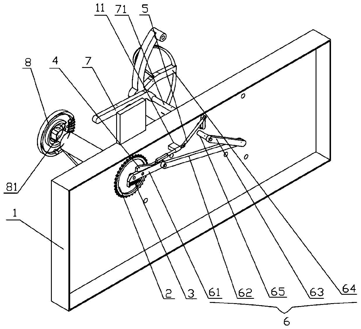
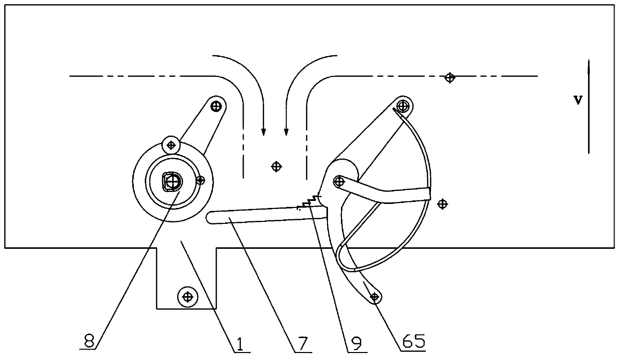
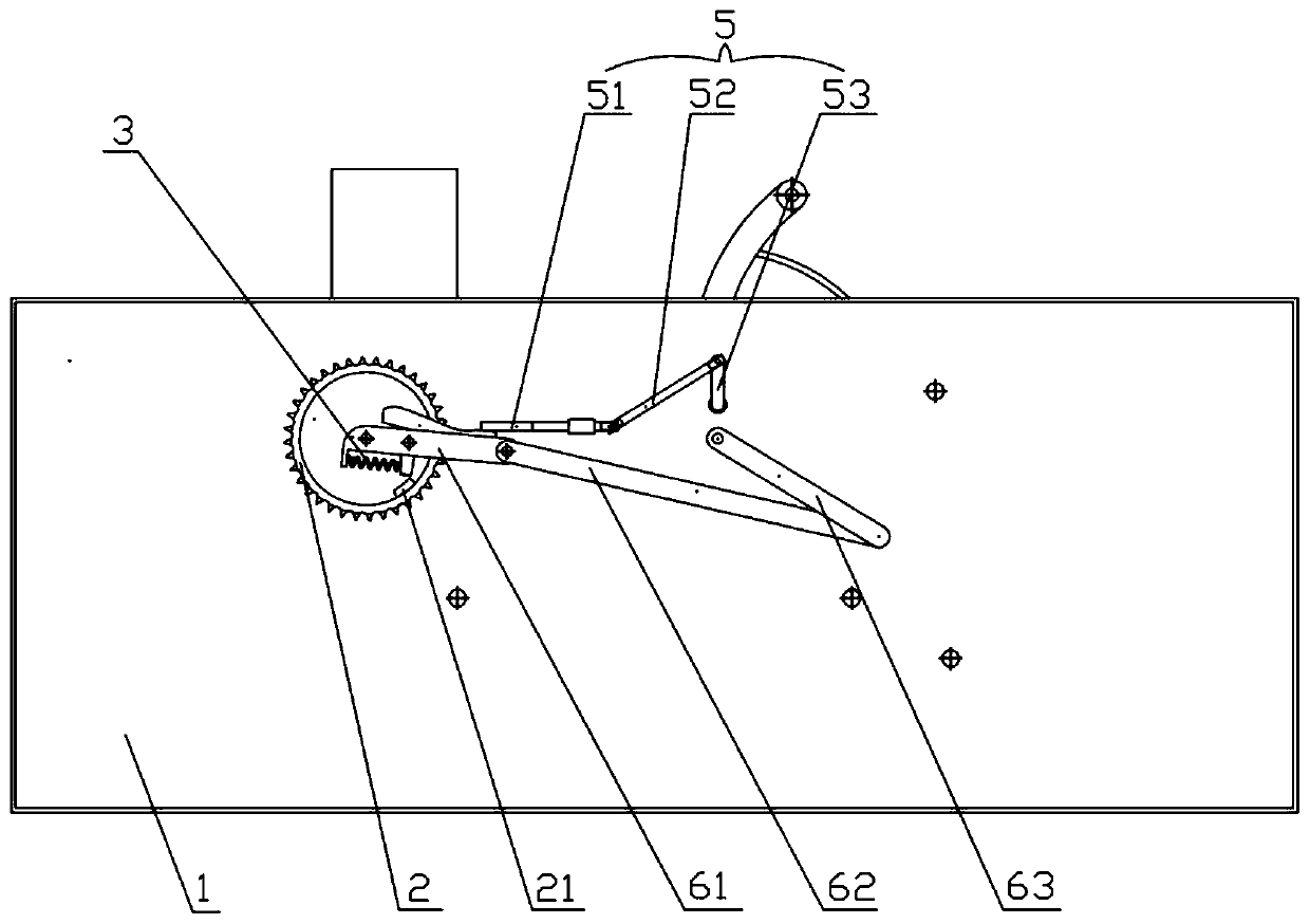
[0026] Such as Figure 1 to Figure 5 As shown, a binding clutch of a baler includes a frame 1, a driving sprocket 2, a compression spring 3, a clutch pawl 4, a clutch control mechanism 5, a rope feeding mechanism 6, a stop rod 7 and a knotter 8 , the knotter 8 is installed on one side of the frame 1 by passing through the knotter shaft 81 of the frame 1, and the drive sprocket 2 is idly sleeved at one end of the knotter shaft 81 located on the other side of the frame 1, and the driving The sprocket 2 is driven by external power, one end of the rope feeding mechanism 6 is keyed to the knotter shaft 81, the clutch pawl 4 is hinged to the end of the rope feeding...


PUM


Abstract

A bale knotting clutch of a binder comprises a rack, a drive sprocket, a compression spring, a clutch claw, a clutch control mechanism, a rope feed mechanism, a baffle rod and a knotter, wherein the knotter is mounted on one side of the rack through a knotter shaft penetrating the rack; the drive sprocket is arranged at one end of the knotter shaft located on the other side of the rack in a loosesleeving manner and driven by external power; one end of the rope feed mechanism is in key joint with the knotter shaft; the clutch claw is hinged with the end part of the rope feed mechanism; one endof the compression spring is connected with the rope feed mechanism, and the other end is connected with the clutch claw; the baffle rod on the same side with the knotter is connected with the clutchcontrol mechanism and can drive the clutch control mechanism to be engaged with and separated from the clutch claw; the clutch control mechanism and the clutch claw are located on the same side of the rack; a shoe block matched with the clutch claw for use is arranged on the drive sprocket; the clutch control mechanism is connected with the baffle rod through a baffle rod shaft; the baffle rod isconnected with a return spring mounted on the rack. The bale knotting clutch of the binder has the characteristics of being simple in structure, fast and thorough in separation and capable of automatically controlling engagement and separation according to bale size.

Description

technical field [0001] The invention relates to a tying device, in particular to a tying clutch of a baler. Background technique [0002] The binding clutch is a key component in the baler to control the rope feeding of the wire feeding needle and the knotting of the knotter. Before the bundling operation of the existing baler, the bundling rope will be installed to form a primary bundling rope. The specific steps are: first, threading the rope by hand. Pass through the rope brake, rope guide (or guide ring), anti-loosening spring, and binding needle (also known as the rope feeding needle) in sequence; second, manually engage the binding clutch, turn the power input member, and make the rope sending needle move The end of the rope is sent to the knotter and clamped by the rope clamping disc to form a primary rope. After starting the operation of the baler, the stalks are continuously accumulated in front of the stop bar and squeezed by the stop bar under the action of the...

Claims


Application Information

Patent Timeline
Patent Type & Authority Patents(China)
IPC IPC(8): A01D37/00
Inventor 杨文敏任述光彭智谭世伟
Owner HUNAN AGRICULTURAL UNIV
Why Eureka
Try Eureka