
Disc ridger

A technology of ridging machine and disc, which is applied in the direction of agricultural machinery and implements, shovels, plows, etc. It can solve the problem of polluted soil, single function, ditches width and ridging height cannot be adjusted according to different crops. problems, to achieve the effect of long service life, stable structure and easy maintenance

Inactive Publication Date: 2019-03-01
薛著平
View PDF0 Cites 0 Cited by
  • Summary
  • Abstract
  • Description
  • Claims
  • Application Information

AI Technical Summary

Problems solved by technology

[0002] The main function of the disc ridger is ditching and ridging. Most of the disc ridging machines currently on the market have a single function. The width of the ditch and the height of the ridging cannot be adjusted according to the cultivation of different crops. One type of ditch width and ridge height can be obtained. However, in actual production, the same piece of land often needs to be cultivated with two kinds of crops in order to maximize the use of land resources. The height of the ridges will also be different, and sometimes there will be some white garbage in the soil. These white garbage are not easy to decompose and pollute the soil. However, the existing disc ridgers can no longer effectively solve the above problems.

Method used


Image

  • Disc ridger
  • Disc ridger

Examples


Embodiment Construction

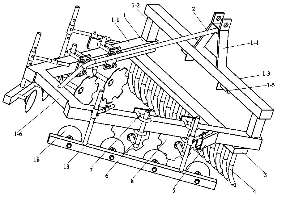
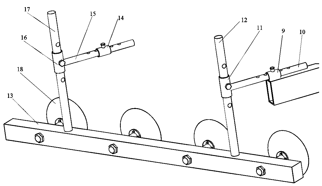
[0014] Such as figure 1 and figure 2 As shown in the schematic diagram of the structure, a disc ridging machine includes a frame 1, and the frame 1 includes sloping plates 1-1 on both sides, and the sloping plates 1-1 on both sides are in the shape of an inverted "eight" outward. Open, the front part of the upper surface of the inclined plates 1-1 on both sides is provided with a column 1-2, the upper end of the column 1-2 is provided with a front beam 1-3, and the middle part of the upper surface of the front beam 1-3 is provided with a suspension arm 1 -4, a pair of fixed shafts 1-5 are arranged in the middle of the lower surface of the front crossbeam 1-3, a through hole is arranged on one side of the fixed shaft, and a rear crossbeam 1-6 is arranged between the rear parts of the inclined plates 1-1 on both sides. A reinforcing bar 2 is arranged between the suspension arm 1-4 and the rear cross beam 1-6, the rear part of the reinforcing bar 2 is an arc structure, and the ...


PUM


Abstract

The invention relates to a disc ridger, comprising a frame, the frame comprises two side inclined plates outwardly opened in an unterminated V shape, the front portions of the upper surfaces of two sides of the frame are provided with upright columns, a front beam is arranged at the upper ends of the upright columns, a rear beam is arranged between the rear portions of two sides of the frame, L-shaped support rods and hollow plates are arranged on the outer side surfaces of two sides of the frame, the ends of the L-shaped support rods are provided with a plurality of notched disc harrow pieces, round rods 1 are horizontally disposed above the hollow plates, the end of one side of each round rod 1 is provided with a sleeve 1, a vertical rod 1 penetrates through each sleeve 1, the lower endof each vertical rod 1 is provided with a rectangular support plate, the rear portions of the upper surfaces of two sides of the frame are horizontally provided with round rods 2, the end of one sideof each round rod 2 is provided with a sleeve 2, a vertical rod 2 penetrates through each sleeve 2, and the inner side surfaces of the rectangular support plates are provided with a plurality of discharrow pieces. Compared with the prior art, the disc ridger has the advantages of stable structure, easy maintenance and long service life.

Description

technical field [0001] The invention belongs to the technical field of agricultural machinery, and in particular relates to a disc ridging machine. Background technique [0002] The main function of the disc ridger is ditching and ridging. Most of the disc ridging machines currently on the market have a single function. The width of the ditch and the height of the ridging cannot be adjusted according to the cultivation of different crops. One type of ditch width and ridge height can be obtained. However, in actual production, the same piece of land often needs to be cultivated with two kinds of crops in order to maximize the use of land resources. The height of the ridges will also be different, and sometimes there will be some white garbage in the soil. These white garbage are not easy to decompose and pollute the soil. However, the existing disc ridgers can no longer effectively solve the above problems. Contents of the invention [0003] In order to solve the existing ...

Claims


Application Information

Patent Timeline
Patent Type & Authority Applications(China)
IPC IPC(8): A01B49/02
CPCA01B49/02
Inventor 盛德兰薛著平赵静凤刘小龙
Owner 薛著平
Learn More