
Brake mechanism capable of being automatically reset

A brake mechanism and automatic reset technology, applied in the field of brake mechanism, can solve troubles and other problems, and achieve the effects of improving safety, convenient operation and simple structure

Pending Publication Date: 2019-03-01
GOODBABY CHILD PROD CO LTD
View PDF1 Cites 1 Cited by
  • Summary
  • Abstract
  • Description
  • Claims
  • Application Information

AI Technical Summary

Problems solved by technology

Therefore, when operating the brake lever, it is necessary to step on the brake lever and lift the brake lever, which is very troublesome.

Method used


Image

  • Brake mechanism capable of being automatically reset
  • Brake mechanism capable of being automatically reset
  • Brake mechanism capable of being automatically reset

Examples


Embodiment Construction

[0034] The present invention will be further described below in conjunction with accompanying drawing and embodiment:

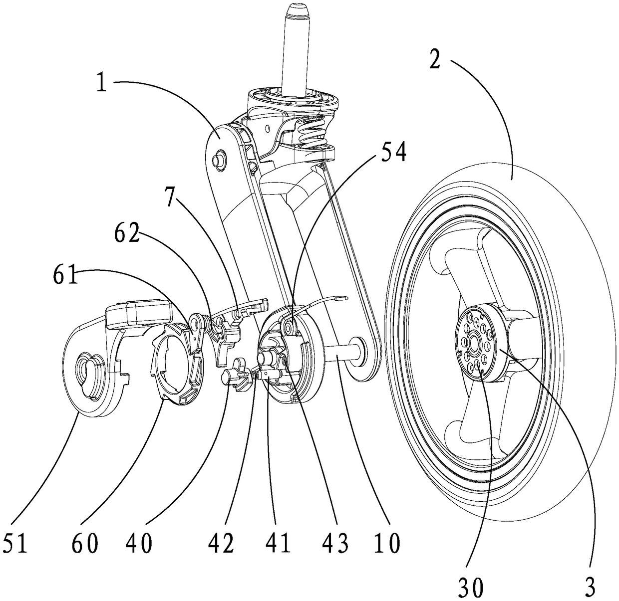
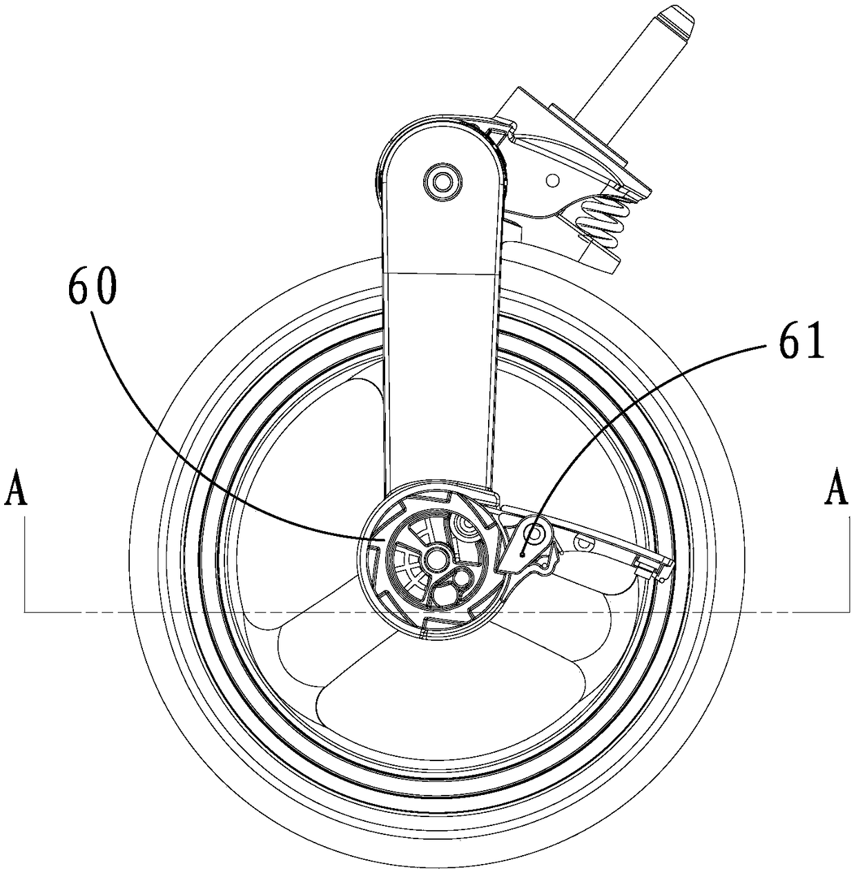
[0035] like figure 1 A self-resetting braking mechanism is shown, which is arranged between the wheel joint 1 and the wheel 2, and the wheel 2 is rotatably set on the wheel joint 1 through the rotating shaft 10.

[0036] The brake mechanism includes a brake disc 3 fixedly arranged on the wheel 2, a brake part that can be matched with or separated from the brake disc 3, and a brake part that is connected to the wheel joint 1 and can rotate around the rotating shaft 10 and is used to align the brake part and the brake disc. 3 engage or disengage the brake handle 50 for operation. In this example:

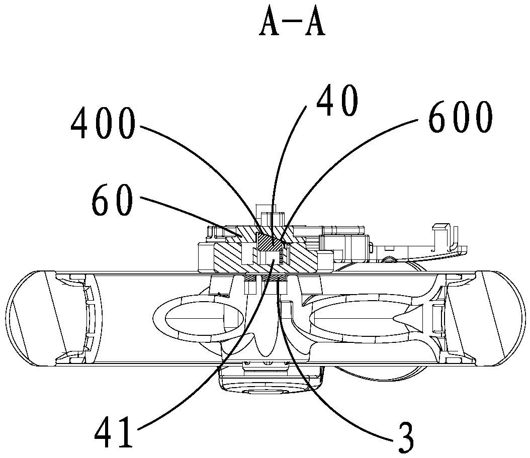
[0037] A plurality of brake holes 30 are opened on the brake disc 3 . The brake parts include a brake pin seat 40 and a brake pin 41 connected to the brake pin seat 40. When the brake pin 41 is matched with the brake disc 3, that is, the brake pin 41 is inserted i...


PUM


Abstract

The invention relates to a brake mechanism capable of being automatically reset. The brake mechanism comprises a brake disc fixedly arranged on a wheel, a brake braking piece, and a brake lever rotatably connected to a wheel joint, and further comprises an intermittent motion mechanism and a brake lever reset piece which are matched with the brake lever and the brake braking piece correspondingly;a plurality of first matching bevel surfaces are arranged on an intermittent motion mechanism; and second matching bevel surfaces are arranged at one end of the brake braking piece. When the brake lever is rotated once, the intermittent motion mechanism moves once, the second matching bevel surfaces of the brake braking piece slide into or side out of the first matching bevel surfaces, the brakebraking piece is matched with or disengaged from the brake disc, thus the brake braking piece enters into a brake state or a brake relieving state, and the brake lever reset piece drives the brake lever to be automatically reset. One-time brake or brake relieving of the wheel is conducted by stepping on the brake lever once, operation is convenient, the structure is simple, and the misoperation condition is avoided, so that the safety of the brake mechanism is improved.

Description

technical field [0001] The invention relates to an automatic reset braking mechanism. Background technique [0002] A stroller includes a frame, a wheel assembly located at the bottom of the frame, and a brake mechanism is usually installed on the wheel assembly (usually the rear wheel). [0003] Refer to the patent with the publication number CN203805966U disclosing a brake mechanism for a stroller. The brake mechanism includes a brake handle pivotally connected to the wheel joint and a brake disc fixed to the wheel. The brake handle has a brake pin, and the brake disc has a There are a plurality of locking blocks distributed in the circumferential direction, and lock grooves are formed between two adjacent locking blocks. The brake handle changes between at least two working positions through the rotation of the relative wheel joint. In the first working position, the brake handle The brake pin on the brake handle breaks away from the lock groove to release the catch bloc...

Claims


Application Information

Patent Timeline
IPC IPC(8): B62B9/08
CPCB62B9/08B62B9/085
Inventor 高翔钱伟桉
Owner GOODBABY CHILD PROD CO LTD
Learn More