
An assembly method of a detachable synchronous locking mechanism placed inside a door leaf

A locking mechanism and assembly method technology, applied in building locks, door/window accessories, building structures, etc., can solve the problems of low transmission efficiency, large transmission torque loss, inconvenient operation, etc., and achieve high transmission efficiency, flexible mechanism, The effect of simple structure

Active Publication Date: 2020-06-09
CHINA INST OF BUILDING STANDARD DESIGN & RES
View PDF7 Cites 0 Cited by
  • Summary
  • Abstract
  • Description
  • Claims
  • Application Information

AI Technical Summary

Problems solved by technology

[0002] At present, when most door leaves are locked with multiple locks, in order to achieve synchronous linkage, an external design is often adopted, which has the problems of large size, large loss of transmission torque, easy damage and rust, and affects the appearance; the locks are packaged in When inside the door leaf, it is difficult to achieve synchronous linkage, which has a great impact on the structure of the door leaf, which will easily reduce the overall stability and safety of the door leaf, and it needs to be disassembled as a whole during maintenance, which can only damage the door leaf, and the maintenance cost is high
In short, most of the existing door locks are complex in structure, inconvenient to operate, low in transmission efficiency, difficult to maintain, and prone to failure

Method used


Image

  • An assembly method of a detachable synchronous locking mechanism placed inside a door leaf
  • An assembly method of a detachable synchronous locking mechanism placed inside a door leaf
  • An assembly method of a detachable synchronous locking mechanism placed inside a door leaf

Examples


Embodiment 1

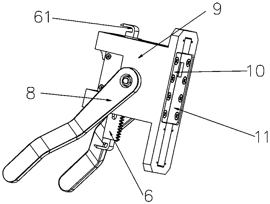
[0039] In the first embodiment, the upper and lower ends of the first rack 6 are provided with hooks 61 for connecting with the hook holes at both ends of the connecting rod.

Embodiment 2

[0040] In the second embodiment, no hook 61 is provided on the upper end of the first rack 6 in the auxiliary lock 2 located at the upper end and the lower end of the first rack 6 in the auxiliary lock 2 located at the lower end.

Embodiment 3

[0041] In the third embodiment, the upper end of the first rack 6 in the auxiliary lock 2 at the upper end and the lower end of the first rack 6 in the auxiliary lock 2 at the lower end are not provided with a hook 61, and a locking head 71 is added for locking Door leaves and upper and lower door frames.

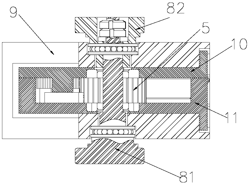
[0042] The main lock 1 is also provided with a handle 8 as an input power, and the handle 8 is fixedly connected with the gear 5 . The handle 8 is used as the input power to drive the gear 5 to rotate, and transmit the torque to the first rack 6 and the second rack 7, and realize the locking assembly through the characteristics of high-precision meshing and high transmission efficiency ratio of the rack and pinion The linkage between and the locking and opening of the door leaf.

[0043] Such as Figure 7 , 8 , 9, further, the main lock 1 and the auxiliary lock 2 also include a fixed seat 9, an upper cover 10 and a lower cover 11, and the upper cover 10 and the lower cov...


PUM


Abstract

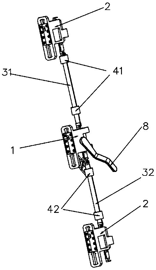
The invention discloses a detachable synchronous locking mechanism in a door leaf and an assembling method. The detachable synchronous locking mechanism comprises a primary lock, secondary locks, a connecting rod and a guider, wherein the primary lock is arranged in the middle of the door leaf and is connected with the secondary locks at the upper and lower ends of the door leaf through the connecting rod; the connecting rod penetrates through the guider and is fixed in the door leaf through the guider; each of the primary lock and secondary locks comprises a gear, a first rack and a second rack; the first racks are vertically arranged, the second racks are horizontally arranged, and the first racks and the second racks are meshed with the gears for transmitting power; a handle for inputting power is arranged on the primary lock and is fixedly connected with the gears; and a mechanical jacking system is connected with a support system through a support arm. The detachable synchronous locking mechanism adopts the detachable design, mounts and detaches the locks without destroying the door leaf, realizes simultaneous opening and closing through the connecting rod, is high in precision and has the advantages of being high in transmission efficiency and simple, compact and flexible in structure.

Description

technical field [0001] The invention relates to the technical field of door leaf locking, in particular to an assembly method of a detachable synchronous locking mechanism placed inside a door leaf. Background technique [0002] At present, when most door leaves are locked with multiple locks, in order to achieve synchronous linkage, most of them adopt an external design, which has the problems of large volume, large loss of transmission torque, easy damage and rust, and affects the appearance; the locks are packaged in When inside the door leaf, it is difficult to achieve synchronous linkage, which has a great impact on the structure of the door leaf, which may easily reduce the overall stability and safety of the door leaf, and the overall disassembly is required during maintenance, which can only damage the door leaf, and the maintenance cost is high. In a word, most of the existing door locks are complex in structure, inconvenient to operate, low in transmission efficien...

Claims


Application Information

Patent Timeline
Patent Type & Authority Patents(China)
IPC IPC(8): E05B63/14E05B15/00E05B3/00E05B17/00
CPCE05B3/00E05B15/00E05B17/0004E05B63/146
Inventor 卢屹东彭飞江漪张瑞龙李姝婷徐泉张学礼王伟凤邢善鹏李瑞海
Owner CHINA INST OF BUILDING STANDARD DESIGN & RES
Learn More