grease pump

A technology for range hoods and smoke panels is applied in the fields of removing range hoods, household stoves/stoves, heating methods, etc., which can solve the problems of different working conditions of range hoods that are unfavorable, and achieve the effects of improving the effect of collecting smoke and improving adaptability.

Active Publication Date: 2020-05-22
WUHU MIDEA SMART KITCHEN APPLIANCE MFG CO LTD
View PDF7 Cites 0 Cited by
  • Summary
  • Abstract
  • Description
  • Claims
  • Application Information

AI Technical Summary

Problems solved by technology

In the existing range hoods, the smoke collecting plate is usually fixedly connected to the frame, or can only be moved up and down simply, so that the working position of the smoke collecting plate is fixed, which is not conducive to the range hood being suitable for different working conditions and cannot meet people’s needs. need

Method used


Image

  • grease pump
  • grease pump
  • grease pump

Examples


Embodiment Construction

[0040] The following will clearly and completely describe the technical solutions in the embodiments of the present invention with reference to the accompanying drawings in the embodiments of the present invention. Obviously, the described embodiments are only part of the embodiments of the present invention, not all of them. Based on the embodiments of the present invention, all other embodiments obtained by persons of ordinary skill in the art without creative efforts fall within the protection scope of the present invention.

[0041] It should be noted that all directional indications (such as up, down, left, right, front, back...) in the embodiments of the present invention are only used to explain the relationship between the components in a certain posture (as shown in the accompanying drawings). Relative positional relationship, movement conditions, etc., if the specific posture changes, the directional indication will also change accordingly.

[0042] In addition, the ...


PUM


Abstract

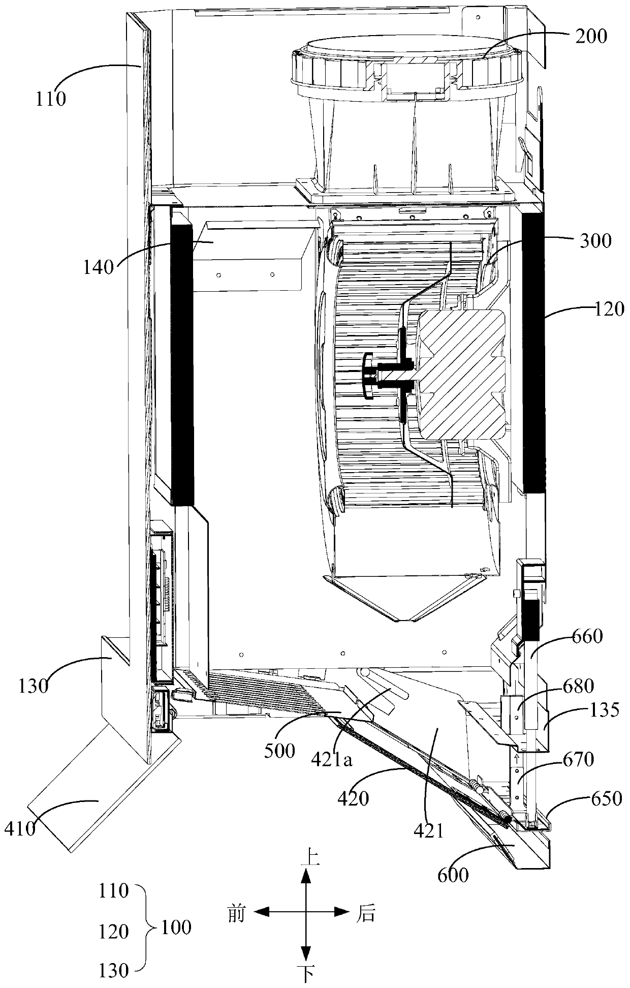
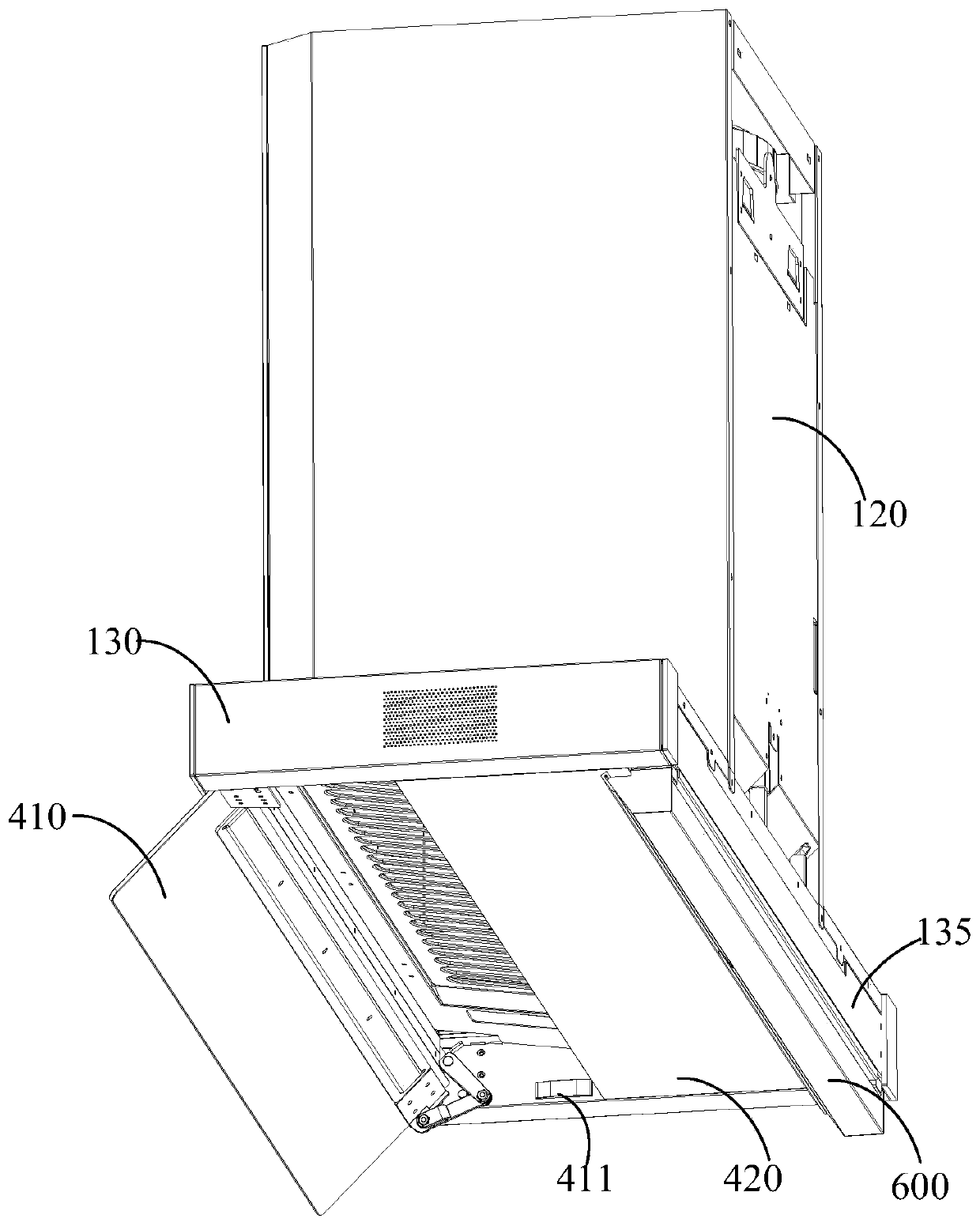
The invention discloses a range hood having a fume collecting chamber and including: a frame; a second fume collecting plate having the rear side connected to the frame in lifting manner, one end of the second fume collecting plate is slidably connected with the frame in a preset path such that the second fume collecting plate may lower and turn to a preset position below the fume collecting chamber. The range hood herein has effectively improved applicability.

Description

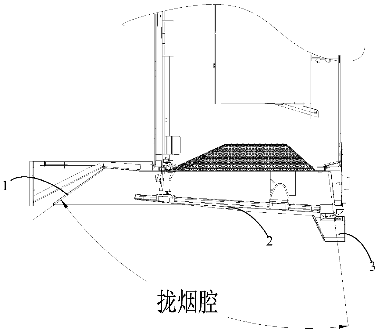
technical field [0001] The invention relates to the technical field of range hoods, in particular to a range hood. Background technique [0002] With the improvement of people's living standards, people have higher and higher requirements for range hoods. Different users have different needs for the position and deflection angle of the smoke collecting plate of the range hood. In the existing range hoods, the smoke collecting plate is usually fixedly connected to the frame, or can only be moved up and down simply, so that the working position of the smoke collecting plate is fixed, which is not conducive to the range hood being suitable for different working conditions and cannot meet people’s needs. need. join figure 1 , the front side wall 1 and the rear side wall of the smoke collection chamber are enclosed to form a smoke collection chamber, the condensation plate 2 is located in the smoke collection chamber, and the oil cup 3 is fixedly arranged on the rear side of th...

Claims


Application Information

Patent Timeline
Patent Type & Authority Patents(China)
IPC IPC(8): F24C15/20
CPCF24C15/2035F24C15/2078
Inventor 邬伟谭柏豪蒋济武黎本锋
Owner WUHU MIDEA SMART KITCHEN APPLIANCE MFG CO LTD
Why Eureka
Try Eureka