Electric pile sealing device and method for sealing electric pile

A sealing device and electric stack technology, which is applied in the direction of circuits, fuel cells, electrical components, etc., can solve problems such as poor effect and difficult sealing, and achieve the effects of increasing life, reducing sealing difficulty, and improving fluency

Pending Publication Date: 2019-03-01
GUANGDONG SUOTE ENERGY TECH CO LTD +1
View PDF7 Cites 3 Cited by
  • Summary
  • Abstract
  • Description
  • Claims
  • Application Information

AI Technical Summary

Problems solved by technology

[0004] Aiming at the current domestic and foreign problems of difficult and poor sealing of fuel cell stacks, the present invention provides a stack sealing device and a method for sealing the stack to solve the deficiencies in the prior art

Method used


Image

  • Electric pile sealing device and method for sealing electric pile
  • Electric pile sealing device and method for sealing electric pile
  • Electric pile sealing device and method for sealing electric pile

Examples


Embodiment 1

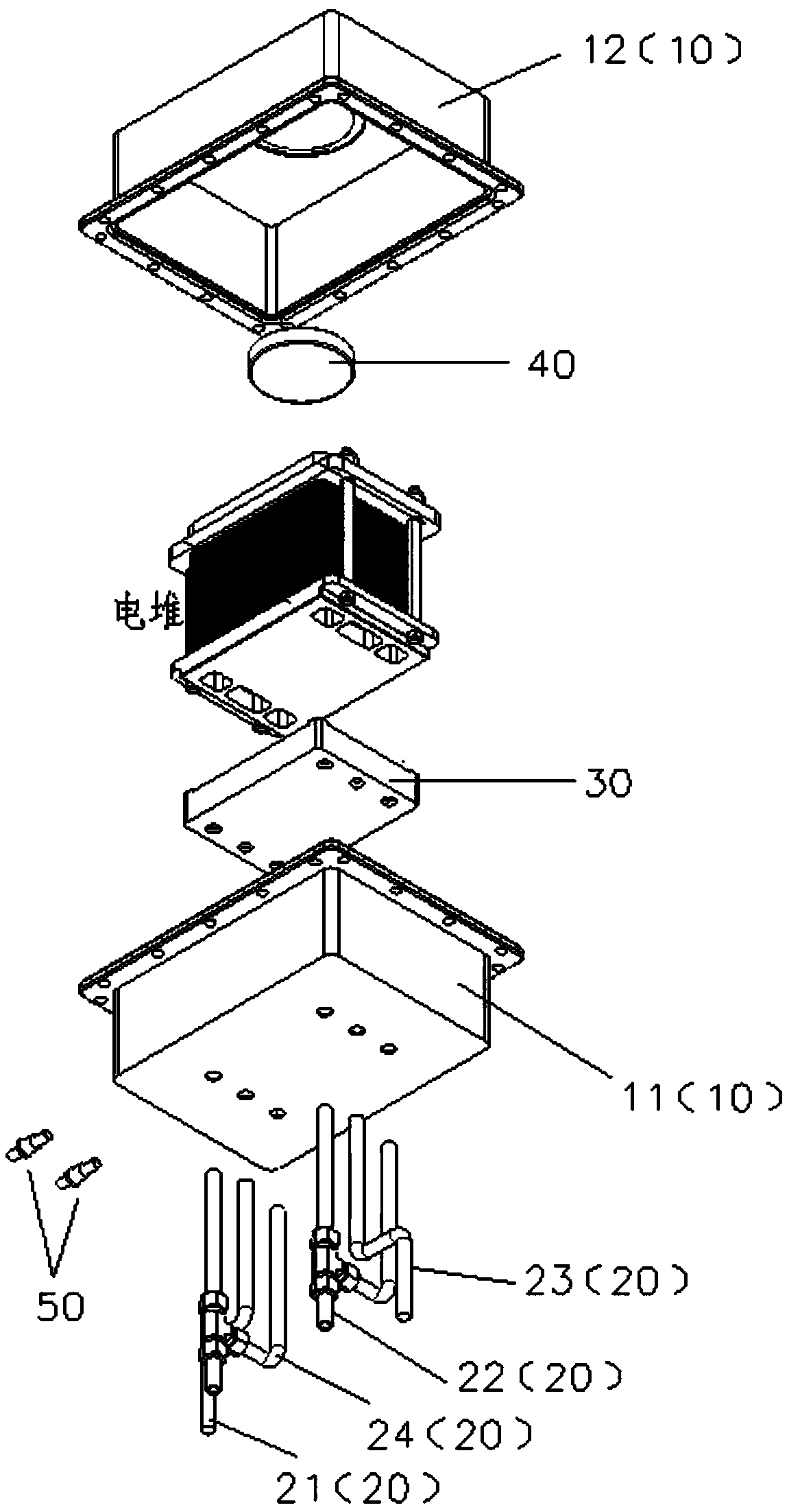
[0033] Such as figure 1 As shown, the embodiment of the present invention provides a stack sealing device, including a sealing box 10 and an air pipe 20, the sealing box 10 includes a lower box 11 and an upper box 12 assembled and installed with each other, the lower box 11 and the The upper boxes 12 are all semi-closed structures, which are combined to form a closed box structure;

[0034] The air pipe 20 is installed on the lower box body 11, one end of the air pipe 20 leaks outside the lower box body 11, and the other end is sealed in the inner cavity of the lower box body 11;

[0035] The bottom of the inner cavity of the lower box 11 is provided with a base 30 for placing a power supply stack, and the positions of the lower box 11 and the base 30 corresponding to the air pipe 20 are provided with through holes for the air pipe 20 to pass through; The side of the lower box 11 is provided with a positive and negative terminal 50;

[0036] The top of the inner cavity of th...

Embodiment 2

[0046] Figure 4 It is a method for sealing an electric stack provided in Embodiment 2 of the present invention. The method is implemented based on the device described in Embodiment 1, and includes the following steps:

[0047] S401. Install the cell stack into the inside of the cell stack sealing device, and feed in cathode gas and anode gas.

[0048] S402. Adjust the gas pressure of the cathode gas and the anode gas, and seal the cell stack, cathode gas and anode gas.

[0049] In order to more clearly demonstrate the implementation process of the solution provided by the embodiment of the present invention, a specific example is given for a detailed introduction.

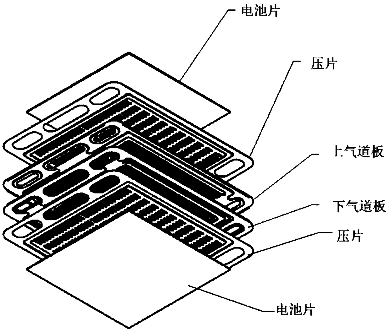
[0050]First of all, put the stack into the inside of the stack sealing device, pass the high-temperature reaction gas from the anode inlet pipe, the anode gas enters from the bottom plate of the stack, and let the anode gas fill the inside of the sealed box through the opening on the top plate of the stack, so t...


PUM


Abstract

The invention discloses an electric pile sealing device and a method for sealing an electric pile. The electric pile sealing device comprises a sealing box and a gas pipe, wherein the sealing box comprises a lower box body and an upper box body; the gas pipe penetrates through the lower box body, one end of the gas pipe is exposed to the outer side of the lower box body, and the other end of the gas pipe is sealed in an inner cavity of the lower box body. A base for placing the electric pile is arranged on the bottom of the inner cavity of the lower box body, and through holes through which the gas pipe penetrates are formed in the positions, corresponding to the gas pipe, of the lower box body and the base respectively. Positive and negative terminals are arranged on the lateral side of the lower box body; a cushion block is arranged on the top of an inner cavity of the upper box body, and a limiting groove for fixing the cushion block is formed in the position, corresponding to the cushion block, of the upper box body. According to the technical scheme, the electric pile is placed in a sealing box, so that the sealing problem is transferred to the relatively simple interior of the sealing box from the complicated interior of the electric pile; moreover, the way of reducing the dropout voltage is adopted, the sealing difficulty is reduced, the electric pile sealing effect is improved, the performance and the power generation efficiency of the electric pile are improved, and the service life of the electric pile is effectively prolonged.

Description

technical field [0001] Embodiments of the present invention relate to the technical field of stack packaging, and in particular, to a stack sealing device and a method for sealing a stack. Background technique [0002] With the country's new energy strategy requirements, high-temperature solid oxide fuel cell (SOFC) is a high-efficiency, clean, quiet and reliable electrochemical power generation device, suitable for distributed, mobile power, auxiliary power, in the entire power generation field has broad application prospects, [0003] However, in the SOFC stack, the sealing material needs to maintain a high degree of sealing performance in a high-temperature environment and an oxidizing environment, and the inside of the stack generally has a large number of layers and a complex structure, and the thermal expansion between each part will increase. The difficulty of sealing, high temperature sealing has always been one of the main technical difficulties affecting the devel...

Claims


Application Information

Patent Timeline
Patent Type & Authority Applications(China)
IPC IPC(8): H01M8/2475H01M8/2485H01M8/0276
CPCH01M8/0276H01M8/2475H01M8/2485Y02E60/50
Inventor 陈东兴沈华涛吴亚攀杨引平韩敏芳夏云峰黄祥乐
Owner GUANGDONG SUOTE ENERGY TECH CO LTD
Why Eureka
Try Eureka