An electrical control cabinet

A technology for electrical control cabinets and cabinets, which is applied to electrical components, electrical equipment shells/cabinets/drawers, cabinets/boxes/drawer parts, etc. , The door switch is inconvenient to operate, the weight of the control cabinet is heavy, etc., to achieve the effect of convenient operation, ensuring structural stability and safety performance, and increasing the compact structure

Active Publication Date: 2020-05-05
泰安泰山高压开关有限公司
View PDF9 Cites 0 Cited by
  • Summary
  • Abstract
  • Description
  • Claims
  • Application Information

AI Technical Summary

Problems solved by technology

[0003] The general structure of the electrical control cabinet is constructed of an external shell and an internal bracket. The internal bracket is used to place various components. The electrical control cabinet is generally in the shape of a cuboid and has a door at the front end. Generally, they are connected to the cabinet body through hinges. When opening the door body, they are generally pulled outward. If it is a double door body, the operator needs to pull it open with two hands or one after another. When closing the cabinet door, two doors are required. The two doors are closed one after the other at the final engagement position, and then the two doors are engaged with each other. Therefore, the existing electrical control cabinet doors have the problem of inconvenient switch operation.
[0004] Due to the material of the electrical control cabinet, the components installed inside it, and the brackets used to install the components inside, the weight of the control cabinet is relatively large. When the control cabinet needs to be moved, it is difficult to carry

Method used


Image

  • An electrical control cabinet
  • An electrical control cabinet
  • An electrical control cabinet

Examples


Embodiment 1

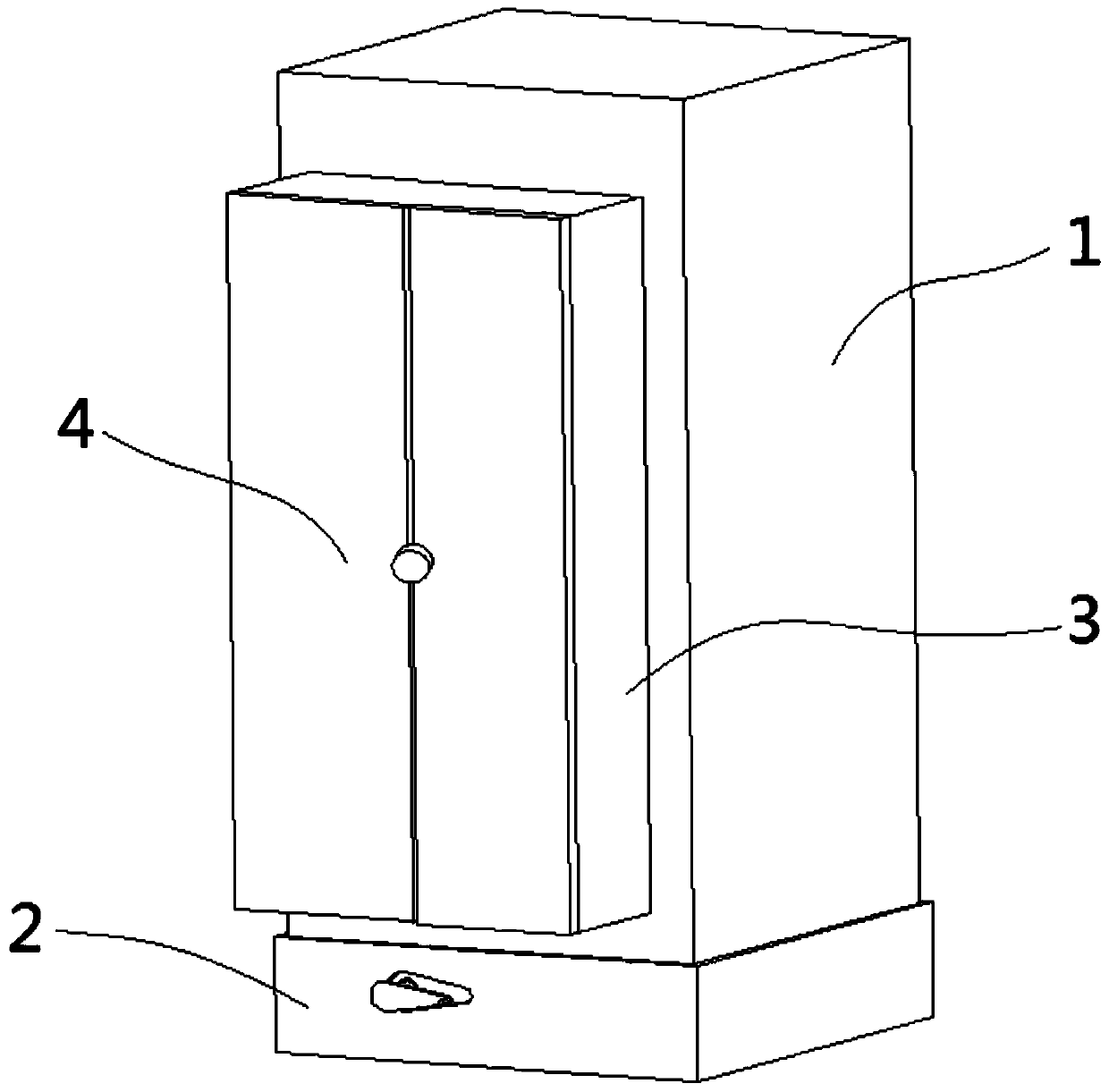
[0043] An electrical control cabinet, such as figure 1 As shown, it includes a cuboid-shaped cabinet body 1 with a built-in cavity, a bracket 11 is placed in the cavity of the cabinet body 1, and required components are installed on the bracket 11 .

[0044] The bottom of the cabinet 1 is provided with a base 2, and the cabinet 1 is fixed on the base 2. The cabinet 1 is provided with a volume expansion body 3 that can protrude from the front end of the cabinet 1 and make a linear reciprocating motion along the width direction of the cabinet 1. The volume The extension body 3 is a rectangular frame body including four side panels and a door body 4 is provided on the front surface. The cavity of body 1 forms a cavity. After opening the door body 4, the components in the cabinet body 1 and the volume expansion body 3 can be observed, and then the internal components can be installed, repaired, replaced and other operations.

[0045] The base 2 is a rectangular frame structure wi...

Embodiment 2

[0068] An electric control cabinet includes a cuboid-shaped cabinet body 1 with a built-in cavity, a bracket 11 is placed in the cavity of the cabinet body 1, and required components are installed on the bracket 11.

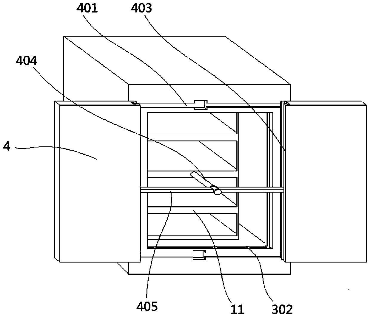
[0069] There is a base 2 at the bottom of the cabinet 1, and the cabinet 1 is fixed on the base 2. There is a door on the front surface of the cabinet 1. After opening the door, the components in the cabinet 1 can be observed, and then the internal components can be checked. Installation, maintenance, replacement and other operations.

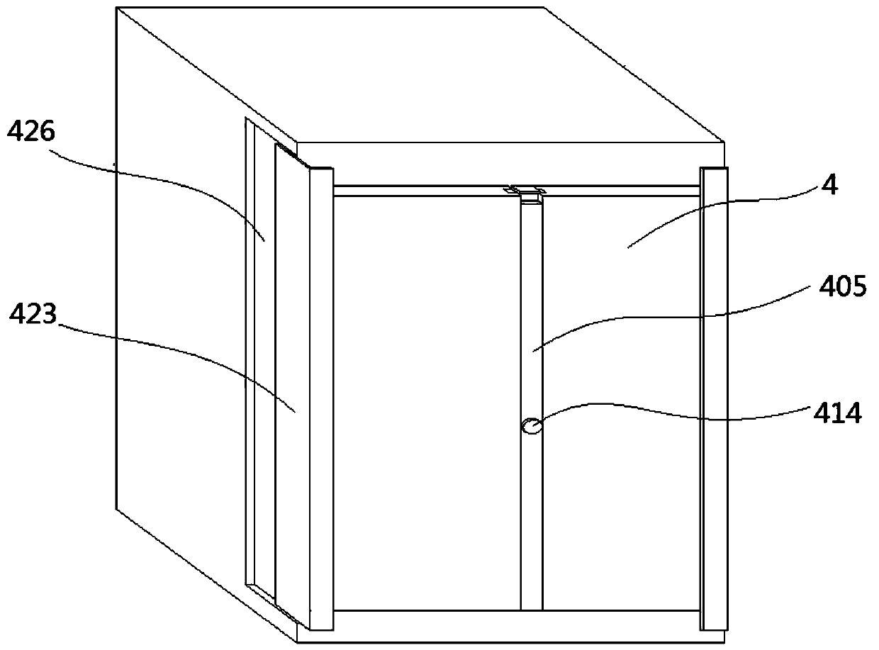
[0070] The base 2 is a rectangular frame structure with a bottom plate 201, and the bottom surface of the cabinet 1 constitutes the top plate 224 of the base 2, such as Figure 2-9 As shown, in the present embodiment, a bracket 11 for placing components is fixed inside the cabinet body 1. The door includes two left and right door bodies 4 located on the same vertical plane. Linear reciprocating motion, wherein the upper end and l...


PUM


Abstract

The invention relates to electrical equipment, and discloses an electrical control cabinet. The electrical control cabinet comprises a left door body and a right door body which are located on the same vertical plane, wherein the two door bodies are arranged oppositely and can do linear reciprocating motion in the relative directions; the electrical control cabinet also comprises a rod assembly used for opening the two door bodies; a walking mechanism is arranged at the bottom of the cabinet body; the walking mechanism comprises a driving part and a walking part, and further comprises a firstscrew rod and a second screw rod which are driven by the driving part; the first screw rod and the second screw rod are in threaded connection with pushing blocks capable of performing linear reciprocating motion along the axial direction of the screw rods respectively; and a walking wheel mechanism is arranged on the pushing blocks. The cabinet door of the electrical control cabinet is designed to be in the form of pushing and pulling on the two sides, and the door bodies can be pushed and pulled through the rod assembly with a rotating rod and a knob, so that the operation is very convenient; and in addition, the walking mechanism capable of extending out of and retracing from the bottom of the cabinet body is additionally arranged, so that the movement of the cabinet body can be easilyrealized.

Description

technical field [0001] The invention relates to electrical equipment, in particular to an electrical control cabinet. Background technique [0002] The electrical control cabinet is a cabinet made of steel to protect the normal operation of components. It is widely used in chemical industry, environmental protection industry, power system, metallurgical system, industry, nuclear power industry, fire safety monitoring, transportation industry, etc. Wait. [0003] The general structure of the electrical control cabinet is constructed of an external shell and an internal bracket. The internal bracket is used to place various components. The electrical control cabinet is generally in the shape of a cuboid and has a door at the front end. Generally, they are connected to the cabinet body through hinges. When opening the door body, they are generally pulled outward. If it is a double door body, the operator needs to pull it open with two hands or one after another. When closing t...

Claims


Application Information

Patent Timeline
Patent Type & Authority Patents(China)
IPC IPC(8): H05K5/02
CPCH05K5/0217H05K5/0234
Inventor 谢长山
Owner 泰安泰山高压开关有限公司
Why Eureka
Try Eureka