Air conditioning unit and vehicular air conditioning device

An air conditioning unit, air technology, applied in vehicle parts, air handling equipment, transportation and packaging, etc., can solve problems such as large operating torque

Active Publication Date: 2019-03-01
MITSUBISHI HEAVY IND THERMAL SYST
View PDF5 Cites 0 Cited by
  • Summary
  • Abstract
  • Description
  • Claims
  • Application Information

AI Technical Summary

Problems solved by technology

[0005] However, in the plate-type damper, the moment will act on the support shaft due to the impact of air-conditioning wind on the damper plate.
When switching the damper, the rotation direction of the damper plate around the support shaft is in the opposite direction to the moment generated by the impact of the air-conditioning wind on the damper plate, and the switching of the damper requires a large operating torque

Method used


Image

  • Air conditioning unit and vehicular air conditioning device
  • Air conditioning unit and vehicular air conditioning device
  • Air conditioning unit and vehicular air conditioning device

Examples


Embodiment Construction

[0038] Hereinafter, an embodiment of an air-conditioning unit and a vehicle air-conditioning apparatus according to the present invention will be described with reference to the drawings.

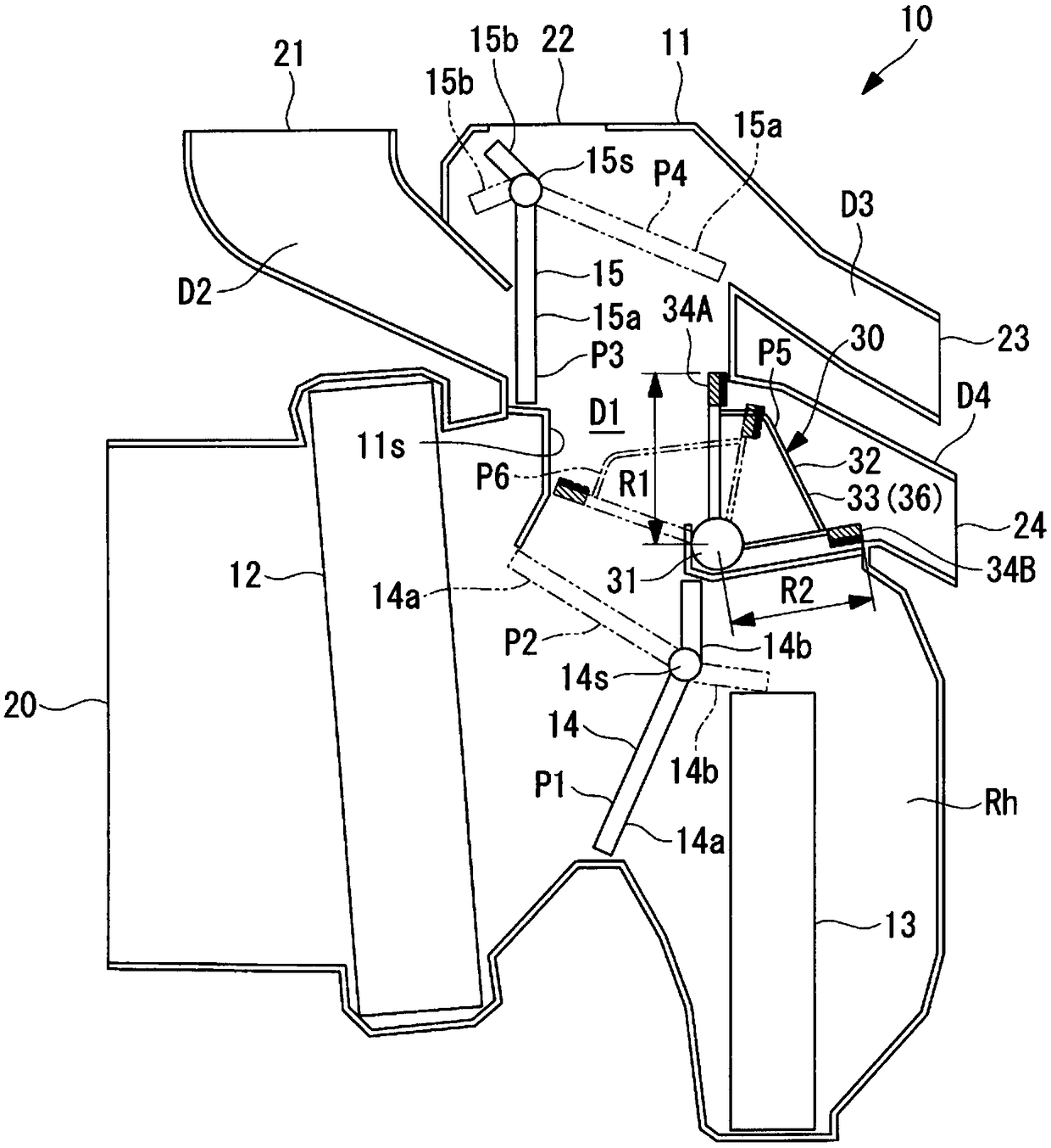
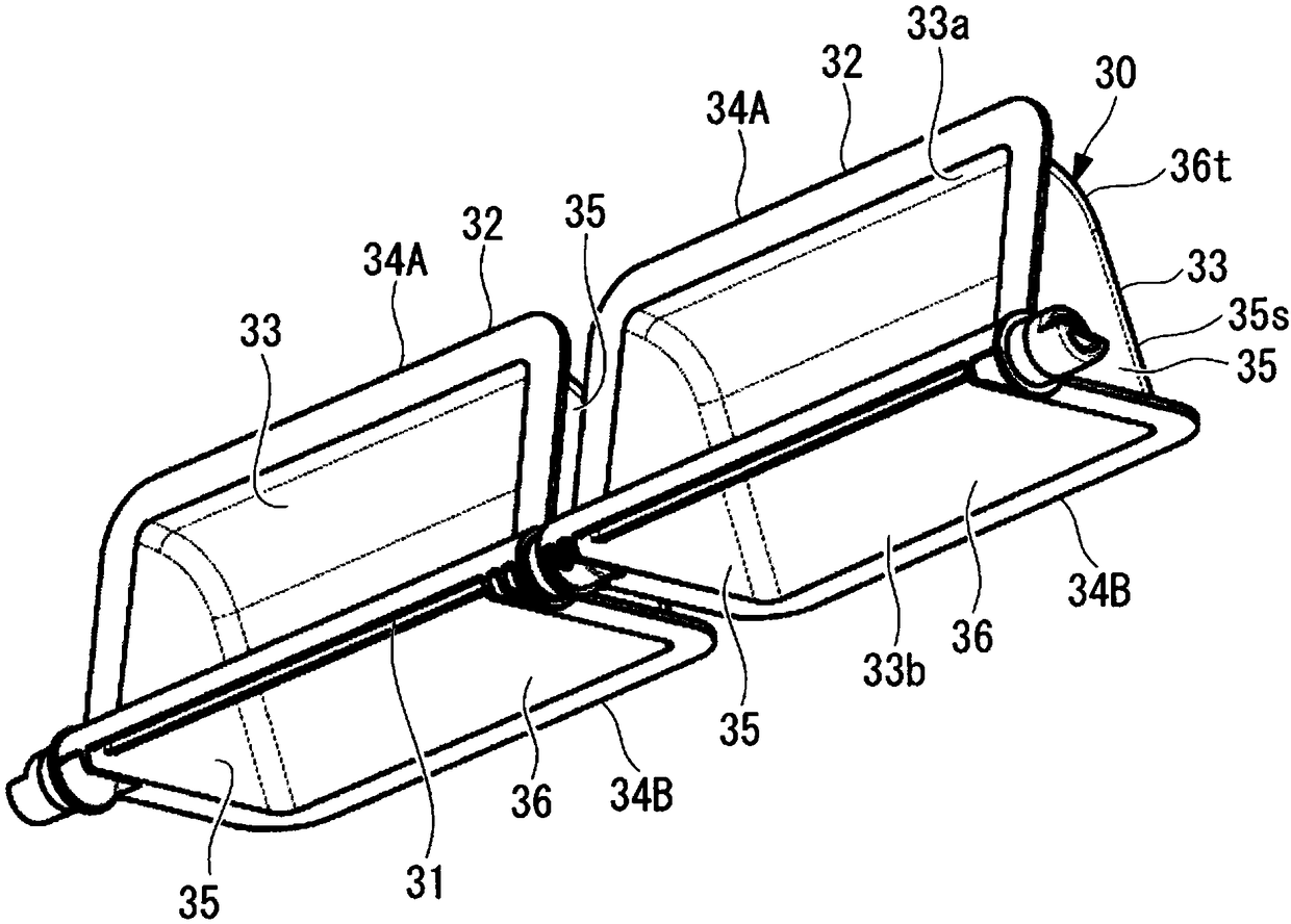
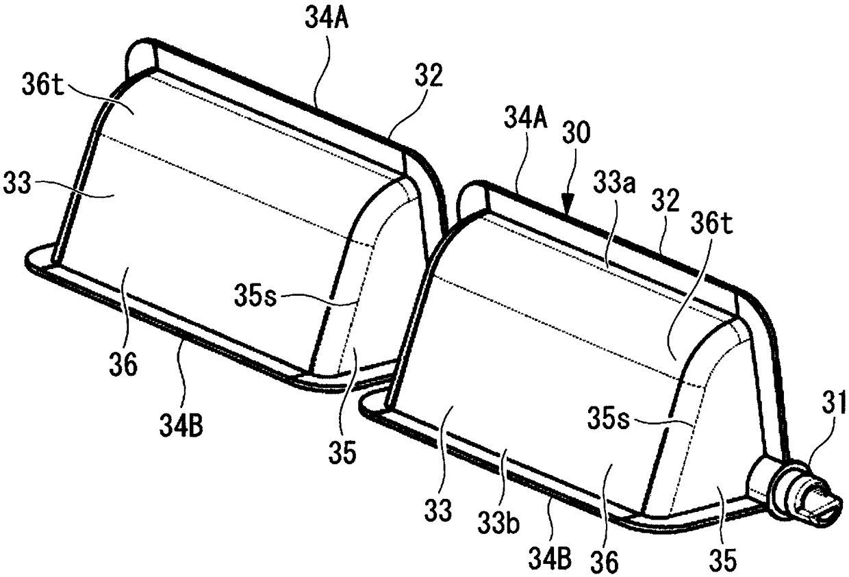
[0039] figure 1 It is a longitudinal sectional view of the air conditioning unit of this embodiment. figure 2 is viewed from the side of the axis of rotation figure 1 A perspective view of the switching damper shown. image 3 Viewed from the guide shield side figure 2 A perspective view of the switching damper shown. Figure 4 yes means figure 1 Enlarged sectional view of the part of the switching damper of the air conditioning unit shown. Figure 5 It is a vertical cross-sectional view of the air conditioning unit in a state where the switching damper protrudes toward the main duct side. Figure 6 It is a longitudinal sectional view of the air conditioning unit in a state where the switching damper is slightly projected toward the main duct side.

[0040] Such as figure 1As shown...


PUM


Abstract

The purpose of the present invention is to provide an air conditioning unit and a vehicular air conditioning device, in which conditioning airflow can be efficiently distributed while increases in thesize of a damper can be minimized. The air conditioning unit is provided with a main duct (D1), a sub duct (D4) that branches from the main duct (D1) and guides air to foot blowout port (24), and a second switching damper (30) provided to the sub duct (D4) in a location facing the main duct (D1). The second switching damper (30) is provided with a rotating shaft (31) and a damper body (32) havinga guiding shroud (33) that is continuous in the circumferential direction around the rotating shaft (31). An end flange (34A) at one circumferential end of the damper body (32) protrudes into the main duct (D1) due to the second switching damper (30) rotating about the rotating shaft (31). The radial dimension (R1) of the end flange (34A) is greater than the radial dimension (R2) of an end flange(34B) at the other circumferential end of the guiding shroud (33).

Description

technical field [0001] The present invention relates to an air conditioning unit and a vehicle air conditioning device. Background technique [0002] The HVAC unit (Heating Ventilation and Air Conditioning Unit: Heating Ventilation and Air Conditioning Unit) installed in the air conditioning system of the vehicle sucks in external air or air in the cabin (internal air) into the air flow path in the unit case, and passes through the evaporator, Heater, and air mixing damper, etc. to adjust the temperature. The air in the cabin is conditioned by selectively blowing temperature-adjusted air-conditioning air from any one of the defrosting outlets, face outlets, and foot outlets formed in the unit case and opening in the cabin. set temperature. [0003] In such a vehicle air conditioner, inside the unit case, various dampers such as an inside-outside air switching damper, an air mixing damper, and a plurality of blowing mode dampers are rotatably supported with respect to the u...

Claims


Application Information

Patent Timeline
Patent Type & Authority Applications(China)
IPC IPC(8): B60H1/00B60H1/12
CPCB60H1/00B60H1/12B60H1/00685B60H1/00064B60H1/00671
Inventor 近川法之
Owner MITSUBISHI HEAVY IND THERMAL SYST
Why Eureka
Try Eureka