Optical film, polarizing plate and liquid crystal display device

a technology of optical film which is applied in the field of optical film, polarizing plate and can solve the problems of uneven display and heavyness of liquid crystal display device, and achieve the effects of reducing humidity dimensional change rate enhancing the molecular alignment of resins, and increasing the tensile elastic modulus of films in the md direction

Active Publication Date: 2017-04-06
FUJIFILM CORP
View PDF0 Cites 0 Cited by
  • Summary
  • Abstract
  • Description
  • Claims
  • Application Information

AI Technical Summary

Benefits of technology

The present invention solves the problem of light leakage in liquid crystal display devices that occurs due to warping of the liquid crystal cell when exposed to high moisture levels. This is achieved by using an optical film that reduces warping by reducing the force generated by shrinkage of the polarizing plate. The optical film is stretched in the MD direction, which also increases the molecular alignment of the resin and reduces the humidity dimensional change rate. The invention uses an acrylic film with a ratio of tensile elastic modulus in the MD direction / tensile elastic modulus in the TD direction of more than 1.36, which further reduces display unevenness.

Problems solved by technology

Meanwhile, when having a large size, the liquid crystal display device becomes heavy.
Due to the elongation of the polarizer, the polarizing plate (the laminated body of the optical film including the polarizer) elongates, and as a result, warpage occurs on a liquid crystal cell to which the polarizing plate is bonded, and a display unevenness (light leakage occurring on four corners of the liquid crystal cell) occurs on the liquid crystal display device.

Method used


Image

  • Optical film, polarizing plate and liquid crystal display device
  • Optical film, polarizing plate and liquid crystal display device
  • Optical film, polarizing plate and liquid crystal display device

Examples


examples

[0210][Manufacture of Film 1]

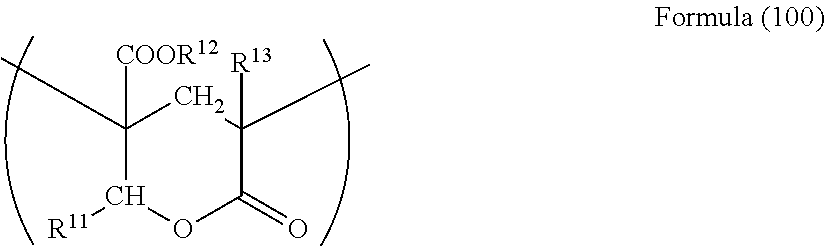
[0211]A pellet of [a mixture of 90 parts by mass of an acrylic resin having a lactone ring structure represented by the following Formula (1) {copolymerization monomer mass ratio=methyl methacrylate / 2-(hydroxymethyl)methyl acrylate=8 / 2, lactone cyclization ratio: about 100%, content ratio of the lactone ring structure: 19.4% by mass, weight average molecular weight: 133,000, melt flow rate: 6.5 g / 10 min (240° C., 10 kgf), Tg: 131° C.} and 10 parts by mass of acrylonitrile-styrene (AS) resin {Toyo AS AS20, manufactured by Toyo-Styrene Co., Ltd.} ; Tg 127° C.] was supplied to a twin-screw extruder and melt-extruded in a sheet form at about 280° C., conveyed with a high tension and wound in a roll form to obtain a long-sized Film 1 having a thickness of 40 μm.

[0212]In Formula (1), Rl is a hydrogen atom, and R2 and R3 are a methyl group.

[0213][Manufacture of Films 2 to 4 and 19]

[0214]Film 2 was manufactured by stretching an unstretched sheet having a thickne...


PUM

PropertyMeasurementUnit
temperature rangeaaaaaaaaaa
mass decreasing temperatureaaaaaaaaaa
glass transition temperatureaaaaaaaaaa

Abstract

There is provided an optical film including an acrylic resin, wherein a tensile elastic modulus in a machine direction, which is abbreviated as an MD direction, and a tensile elastic modulus in a direction perpendicular to the machine direction, which is abbreviated as a TD direction, satisfy the relationship of Equation (1): Equation (1) Tensile Elastic Modulus in the MD Direction / Tensile Elastic Modulus in the TD Direction>1.36.

Description

CROSS-REFERENCE TO RELATED APPLICATION(S)[0001]The present application application is a continuation application of parent U.S. application Ser. No. 14 / 199,424, filed on Mar. 6, 2014, which claims priority from Japanese Patent Application Nos. 2013-046651 filed on Mar. 8, 2013, 2013-079969 filed on Apr. 5, 2013, and 2013-090647 filed on Apr. 23, 2013, the entire contents of which are incorporated herein by reference.BACKGROUND[0002]1. Field[0003]The present invention relates to an optical film, a polarizing plate and a liquid crystal display device.[0004]2. Description of Related Art[0005]The liquid crystal device is a space-saving image display device with low electric power consumption, and the use thereof is increasing every year. A wide viewing angle liquid crystal mode such as a VA mode and an IPS mode is being put into practice, and accordingly, the demand for a liquid crystal display device is rapidly spreading even in the market where a high-quality image such as a televisio...

Claims


Application Information

Patent Timeline
Patent Type & Authority Applications(United States)
IPC IPC(8): G02F1/1335
CPCG02F1/133528G02F2001/133567G02F2001/133562G02B5/3083G02F1/133562G02F1/133567
Inventor ISHIGURO, MAKOTOARITA, SHUSUKE
Owner FUJIFILM CORP
Why Eureka
Try Eureka