Paint conveyor with controllable conveying efficiency

A conveyor and paint technology, applied to mixers, mixer accessories, dissolution, etc., can solve problems affecting construction efficiency, increase mixing time, paint accumulation, etc., to facilitate paint circulation, speed up paint circulation, and low cost Effect

Inactive Publication Date: 2019-03-05
刘荣伟
View PDF0 Cites 0 Cited by
  • Summary
  • Abstract
  • Description
  • Claims
  • Application Information

AI Technical Summary

Problems solved by technology

At present, when feeding materials into the mixer, various paints are usually directly added into the mixer according to the specific ratio, and the paint is easy to accumulate in the mixer. In order to ensure that the paint is fully mixed, it is often necessary to increase the mixing time. This will affect the construction efficiency

Method used


Image

  • Paint conveyor with controllable conveying efficiency

Examples


Embodiment

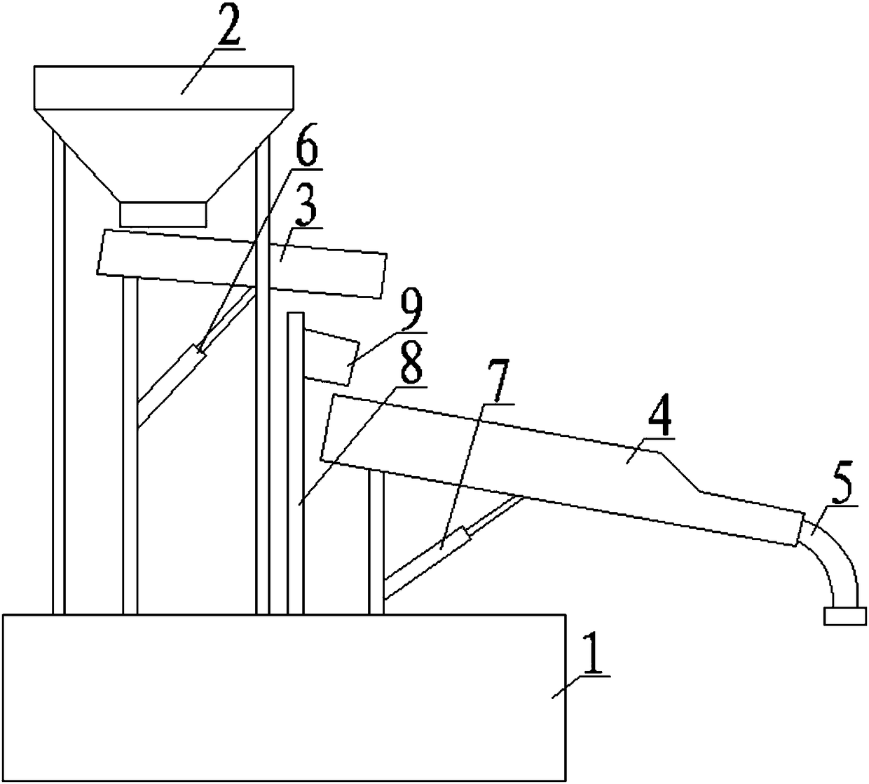
[0016] Such as figure 1 As shown, the paint conveyor with controllable transmission efficiency includes a support platform 1, a conical feed trough 2, a first open trough 3, a second open trough 4, a first telescopic support 6, a second telescopic support 7, and a mounting column 8 and an aerator 9, wherein the support platform 1 is provided with a plurality of columns supporting the conical feeding tank 2. The first open slot 3 and the second open slot 4 are all left high and right low inclined, the first open slot 3 is open at the right end, the second open slot 4 is open at both left and right ends, and the left end of the first open slot 3 is located on the tapered feed Below the groove 2, and the lower end of the tapered feeding groove 2 is centered and facing the first opening groove 3 groove body. The left end of the second open slot 4 is located below the first open slot 3 , and the right end of the first open slot 3 is located directly above the body of the second op...


PUM


Abstract

The invention discloses a paint conveyor with controllable conveying efficiency. The paint conveyor comprises a conical feeding groove, a first opening groove, a second opening groove, a first telescopic support, a second telescopic support, a mounting column and an aerator, wherein the first opening groove and the second opening groove are both obliquely arranged with a higher left part and a lower right part; the right end of the first opening groove is open; the left end and the right end of the second opening groove are both open; the left end of the first opening groove is arranged belowa conical feeding groove; and the left end of the second opening groove is arranged below the first opening groove. The first telescopic support and the second telescopic support both comprise a supporting column, a positioning cylinder, a supporting rod and an elastic piece, wherein the upper end of the supporting column of the first telescopic support and the right end of the supporting rod of the first telescopic support are both fixed at the bottom of the first opening groove; and the upper end of the supporting column of the second telescopic support and the right end of the supporting rod of the second telescopic support are both fixed at the bottom of the second opening groove. The mounting column is fixed on a supporting platform, the aerator is fixed on the mounting column, and anair outlet of the aerator right faces to the left end opening of the second opening groove. The paint conveyor is used for transition of oil paint during oil paint mixing, and oil paint mixing efficiency can be improved.

Description

technical field [0001] The invention relates to the field of furniture production, in particular to a paint conveyor with controllable transmission efficiency. Background technique [0002] Paint plays a protective and aesthetic role on the surface of furniture products. In order to make the product more beautiful, there are more and more colors of paint. The traditional color mixing method is to mix different paints together, and then mix them manually. The way of manual mixing is low in work efficiency, uneven force can easily lead to uneven mixing of paint, uneven color of each bucket of paint, and serious waste. And long-term contact with paint will cause damage to the human body, and there is a certain danger. In order to overcome the above problems, people use a mixer to mix the paint. At present, when feeding materials into the mixer, various paints are usually directly added into the mixer according to the specific ratio, and the paint is easy to accumulate in the ...

Claims


Application Information

Patent Timeline
Patent Type & Authority Applications(China)
IPC IPC(8): B01F15/02
CPCB01F35/712B01F35/717B01F2101/30
Inventor 刘荣伟
Owner 刘荣伟
Why Eureka
Try Eureka