
Method of voltage drop compensation on USB c-type cable and corresponding circuit

A voltage drop and compensation power supply technology, which is applied in the direction of electrical components, adjusting electrical variables, electrical digital data processing, etc., can solve the problems of controller performance or low power consumption efficiency, and achieve the effect of small area and power consumption

Active Publication Date: 2019-03-05
STMICROELECTRONICS SRL
View PDF5 Cites 0 Cited by
  • Summary
  • Abstract
  • Description
  • Claims
  • Application Information

AI Technical Summary

Problems solved by technology

[0012] Therefore, conventional controllers are not efficient in terms of performance or power consumption, especially when there is no load or a small connected load

Method used


Image

  • Method of voltage drop compensation on USB c-type cable and corresponding circuit
  • Method of voltage drop compensation on USB c-type cable and corresponding circuit
  • Method of voltage drop compensation on USB c-type cable and corresponding circuit

Examples


Embodiment Construction

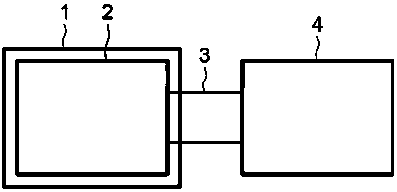
[0046] figure 1An electronic device 1 is illustrated, in this case for example a desktop or laptop computer 1, comprising at least one USB Type-C source device 2 capable of communicating to a USB Type-C sink device 4 (in In this case, such as a cellular mobile phone) charging.

[0047] For simplicity, only one source device 2 of the electronic device 1 is shown here.

[0048] Such as figure 2 As shown in , both the source device 2 and the sink device 4 include a female connector 5, which includes two channel configuration pins CC1 and CC2, four supply voltage pins VBUS and four ground pins GND .

[0049] As defined in the USB 3.1 Type C standard, all pins of the same type described above are symmetrical about the center of the connector 5 so that the connector 5 has no insertion direction.

[0050] The USB Type-C cable 3 includes two male cable connectors 6 ( image 3 ), each cable connector 6 contains the channel configuration pin CC of the cable 3, which is designed t...


PUM


Abstract

The present invention provides a method used for compensating a voltage drop on a cable connected between a source device and a receiver device. The source device delivers an offset current on a channel configuration pin of the source device, the offset current causing an increase in a voltage on the channel configuration pin of the source device to a chosen reference voltage. The offset current is stored in the source device. The source device absorbs an absorption current originating from the channel configuration pin of the source device, the absorption current depending on the stored offset current and on the voltage drop. The source device generates a compensated supply voltage on a power supply pin of the source device, the compensated supply voltage equal to a reference supply voltage increased by the voltage drop to within a tolerance.

Description

[0001] Cross References to Related Applications [0002] This application claims the benefit of French Patent Application No. 1758133 filed on September 04, 2017, which is incorporated herein by reference. technical field [0003] Embodiments relate to methods and corresponding circuits for voltage drop compensation on cables. Background technique [0004] USB Type-C (USB Type-C) cables are generally designed to be coupled between a so-called USB Type-C 'source' device and a so-called USB Type-C 'sink' device, and establish power and communication between the two line. [0005] In theory, USB Type-C devices enable bit rates up to 10Gb / s and deliver up to 100W via the power pin known to those skilled in the art by the acronym 'VBUS' [0006] (wherein the maximum voltage is 20V, the maximum current is 5A) power becomes possible. [0007] This high current of 5A present in a USB Type-C cable usually results in a large voltage drop. As a result, the effective voltage receiv...

Claims


Application Information

Patent Timeline
Patent Type & Authority Applications(China)
IPC IPC(8): G05F1/56
CPCG05F1/56G05F1/563G06F1/266G05F1/462H02M1/0022H02M1/0096G05F5/00H02M3/156
Inventor A·庞斯
Owner STMICROELECTRONICS SRL
Learn More