Vibration-damping installation structure and method of functional modules in sub-boxes, and sub-boxes

A technology of functional modules and installation structures, applied in the direction of support structure installation, installation plate safety devices, clamping/extracting devices, etc., can solve the problems of unsolved guide rails and the inability to tighten bolts, etc., to improve the coordination stability and structure Simple, vibration-reducing effect

Active Publication Date: 2021-02-09
CSR ZHUZHOU ELECTRIC LOCOMOTIVE RES INST
View PDF12 Cites 0 Cited by
  • Summary
  • Abstract
  • Description
  • Claims
  • Application Information

AI Technical Summary

Problems solved by technology

In this solution, the guide rail is pressed into the bracket by pressing blocks, rubber heat and bolts to reduce the deceleration between the guide rail and the bracket, but the functional modules in the sub-box need to be pulled out of the sub-box quickly and conveniently for The bolts that hold down the guide rails are located on both sides and in the middle of the bracket, making it impossible to fast and conveniently tighten the bolts and pull the functional modules out of the sub-box
[0007] Although the above two patents relate to the anti-loosening and vibration reduction of the guide rail, they do not solve the problems existing in the guide rail mentioned above. Therefore, the installation structure of the functional modules in the existing subrack is improved by reducing the distance between the guide rail and the chute. Vibration, reducing the vibration of functional modules is the research direction of the present invention

Method used


Image

  • Vibration-damping installation structure and method of functional modules in sub-boxes, and sub-boxes
  • Vibration-damping installation structure and method of functional modules in sub-boxes, and sub-boxes
  • Vibration-damping installation structure and method of functional modules in sub-boxes, and sub-boxes

Examples


Embodiment 1

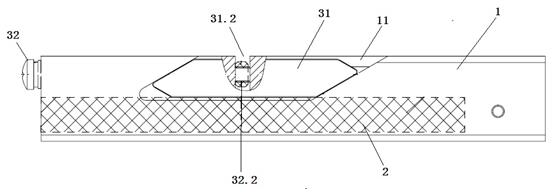
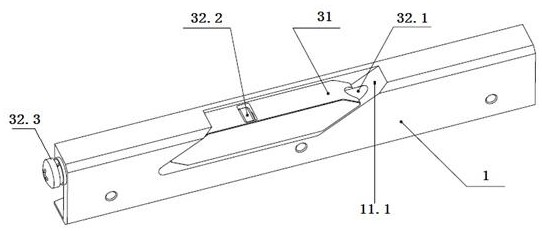
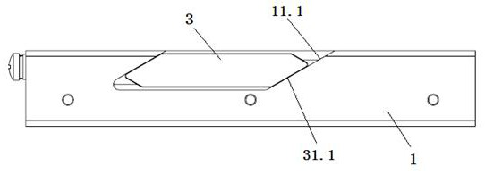
[0034] A vibration-damping installation structure of a functional module in a box, comprising a chute 1 installed in the box and a guide rail 2 installed on the functional module, the guide rail 2 slides and fits with the chute 1 and is inserted into the chute 1, and the The functional module is installed in the sub-box, and it is characterized in that the vibration-damping and compressing device 3 is installed on the chute 1, and the vibration-damping and compressing device 3 moves on the chute 1 to compress the guide rail 2 or loosen the pair The compression of rail 2.

[0035] The vibration damping and pressing device 3 includes a wedge-shaped pressing block 31 and a screw assembly 32, the wedge-shaped pressing block 31 and the screw assembly 32 are arranged along the length direction of the chute 1, and the wedge-shaped pressing block 31 is located directly above the guide rail 2, And not in contact with the guide rail 2, the two sides of the wedge-shaped pressing block 31...


PUM


Abstract

The vibration-damping installation structure and method of the functional module in the sub-box, including the chute installed in the sub-box and the guide rail installed on the functional module, the guide rail and the chute slide and fit into the chute, and the functional module is installed In the box, it is characterized in that the vibration-damping and pressing device is installed on the chute, and the vibration-damping and pressing device moves on the chute to compress the guide rail or loosen the compression on the guide rail. In the present invention, the installation stability of the functional modules in the sub-box is higher, which can effectively reduce the vibration of each functional module in the sub-box in the vehicle-mounted state, and reduce the wear of the guide rail and the chute, and the installation reliability of the functional modules is higher. The service life is longer, and the operation safety of the equipment in the box is higher. The invention also provides a plug-in box.

Description

technical field [0001] The invention relates to a vibration-damping installation structure and method of a functional module in a sub-box, which is used to reduce the vibration of the functional module in the sub-box in a vehicle state. The invention also relates to a sub-box. Background technique [0002] Traction drive system is the "heart" unit of rail transit vehicle equipment to realize electromechanical energy conversion. Its performance determines the power quality, energy consumption and control characteristics of rail transit vehicles to a certain extent, and is the key to energy-saving upgrade of rail transit. As the core components of the traction drive system, the converter controller and network controller are integrated in the traction drive controller sub-box. [0003] As the product integration becomes higher and higher, more and more functions are given to the subrack. In addition to commonly used plug-ins, some larger functional module units are often integ...

Claims


Application Information

Patent Timeline
Patent Type & Authority Patents(China)
IPC IPC(8): H05K7/14
CPCH05K7/1407H05K7/1418
Inventor 徐军杨勇张文辉张强许倍倍罗关张璐鄢慧文
Owner CSR ZHUZHOU ELECTRIC LOCOMOTIVE RES INST
Why Eureka
Try Eureka