
Filtering machine

A technology of filter material and filter screen, which is applied in the field of filter material machine, can solve the problems of unfavorable material filtration and separation, inconvenient material filtration and separation, complex structure of filter material machine, etc., and achieve fast and efficient filtration and separation, convenient filtration and separation, and convenient filtration and separation Effect

Pending Publication Date: 2019-03-08
ANHUI XINONG AGRI DEV
View PDF8 Cites 0 Cited by
  • Summary
  • Abstract
  • Description
  • Claims
  • Application Information

AI Technical Summary

Problems solved by technology

[0002] In the processing industry, when materials need to be filtered, the traditional filter machine is not conducive to quickly and efficiently realize the filtration and separation of materials, and the traditional filter machine has a complex structure, which is not conducive to use, thus causing material Filtration separation becomes more inconvenient

Method used


Image

  • Filtering machine
  • Filtering machine
  • Filtering machine

Examples


Embodiment Construction

[0018] The technical solutions in the embodiments of the present invention will be clearly and completely described below in conjunction with the accompanying drawings in the embodiments of the present invention. Obviously, the described embodiments are only a part of the embodiments of the present invention, rather than all the embodiments.

[0019] In the description of the present invention, it should be understood that the terms "upper", "lower", "front", "rear", "left", "right", "top", "bottom", "inner", " The orientation or positional relationship indicated by “outside” is based on the orientation or positional relationship shown in the drawings, and is only for the convenience of describing the present invention and simplifying the description, and does not indicate or imply that the device or element referred to must have a specific orientation to The specific azimuth structure and operation cannot be understood as a limitation of the present invention.

[0020] Reference ...


PUM


Abstract

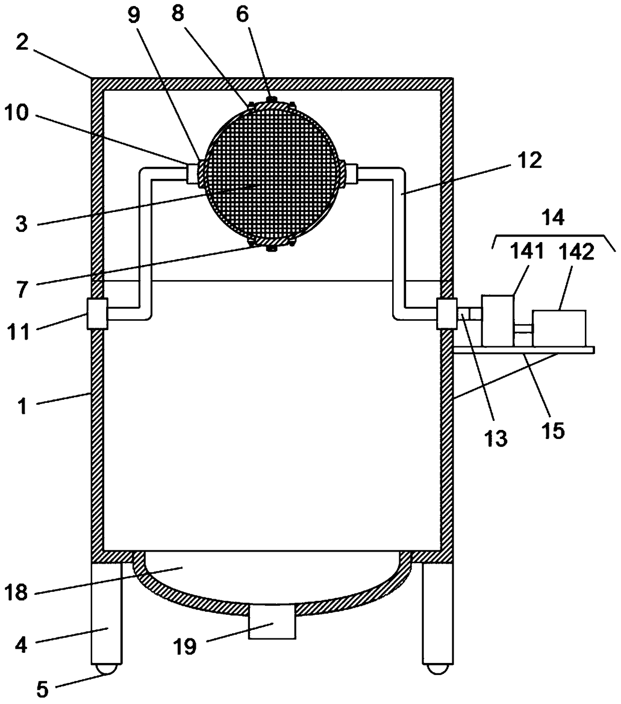
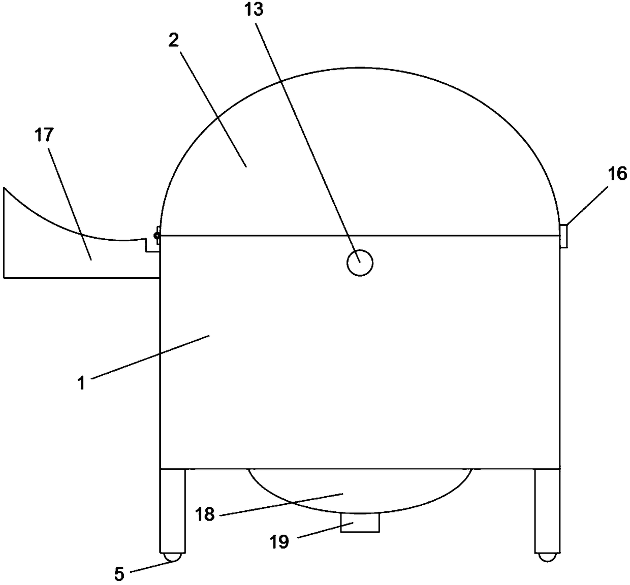
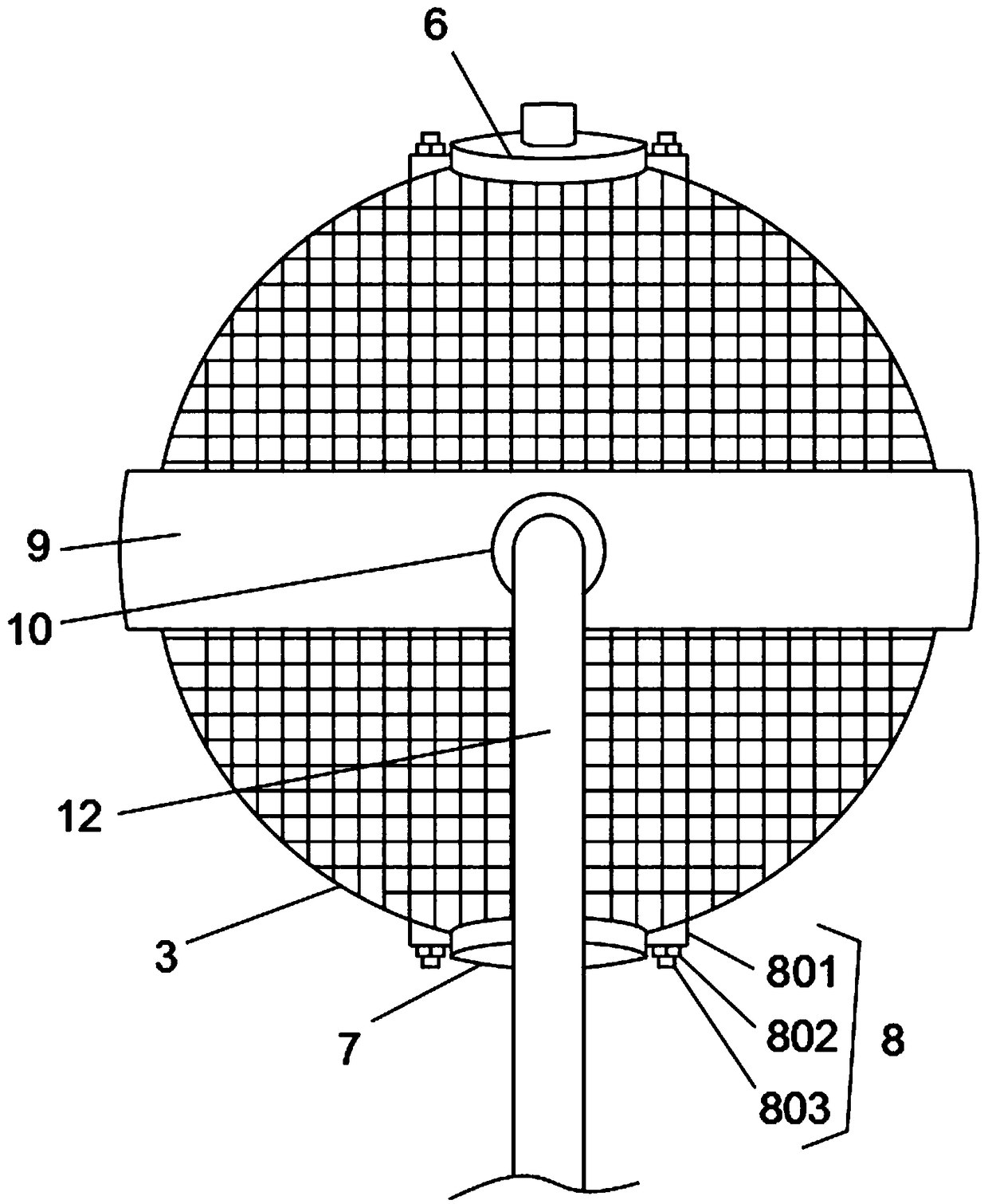
The invention discloses a filtering machine which comprises a filtering cabin and a cabin cover, wherein the cabin cover is hinged with one side of the upper end surface of the filtering cabin by using a hinge; a spherical filtering net is arranged in the center above the upper end of the filtering cabin; the middle part of the outer surface of the spherical filtering net is sleeved by a sleeve ring in a horizontal state; first rotating bases are fixedly connected with both sides of the outer circular surface of the sleeve ring; second rotating bases are arranged corresponding to the first rotating bases on both sides of the upper end of the filtering cabin; Z-shaped connecting rods are connected between the second rotating bases and the first rotating bases close to each other; a rotatingshaft is connected to one end inside the second rotating base on one Z-shaped connecting rod; the other end of the rotating shaft extends out of the filtering cabin and is connected with a power component; openings are formed in end surfaces of the upper end and the lower end of the spherical filtering net; a feeding door and a discharge door are respectively mounted at the openings. The filtering machine is capable of rapidly and efficiently filtering and separating materials, and is simple and convenient to operate in the use process, and convenient to use.

Description

Technical field [0001] The invention relates to the technical field of material filtering, in particular to a filter material machine. Background technique [0002] In the processing industry, when materials need to be filtered, the use of traditional filter media is not conducive to the rapid and efficient realization of the filtration and separation of materials, and the traditional filter media is complex in structure and is not conducive to use, thus causing materials The filtration separation becomes more inconvenient. To this end, we have proposed a filter material machine. Summary of the invention [0003] The purpose of the present invention is to solve the shortcomings existing in the background art, and propose a filter material machine. [0004] In order to achieve the above objectives, the present invention adopts the following technical solutions: [0005] A filter material machine includes a filter bin and a bin cover. The bin cover is hinged on one side of the upper ...

Claims


Application Information

Patent Timeline
Patent Type & Authority Applications(China)
IPC IPC(8): B01D33/76B01D33/333B01D33/80
CPCB01D33/333B01D33/76B01D33/801B01D33/803
Inventor 苏起升
Owner ANHUI XINONG AGRI DEV
Learn More