Check patentability & draft patents in minutes with Patsnap Eureka AI!

Slidable smoke absorption trapping and blowing device

A blowing device, smoke hood technology, applied in the direction of dust removal, metal processing machinery parts, maintenance and safety accessories, etc., can solve the problem of endangering the health of workers and the workshop environment, affecting the health of cutting operators, and failing to achieve better smoke and dust collection Collection effects and other issues

Inactive Publication Date: 2019-03-08
WELLDONE ENVIRONMENTAL PROTECTION EQUIP CHANGSHA
View PDF13 Cites 3 Cited by
  • Summary
  • Abstract
  • Description
  • Claims
  • Application Information

AI Technical Summary

Problems solved by technology

[0002] The CNC cutting machine will generate a lot of smoke and dust during the cutting process. These smoke and dust will generally spread around due to the cutting force, which will not only affect the health of the cutting operator, but also adversely affect the normal progress of the cutting process. Therefore, it is necessary to This part of the smoke and dust is collected and then dedusted by dust removal equipment
However, most of the existing CNC cutting machine dust removal and smoking devices do not have the blowing function. When the cutting span exceeds a certain range, the smoking function gradually decays when the cutting torch is far away from the smoking device, and the smoke cannot be completely captured and diffused into the working environment. Seriously endanger the health of workers and the environment of the workshop; although some have the function of blowing, the position of the blowing device is generally constant, so for mobile cutting machines, it cannot achieve a good dust collection effect, and further improvement is needed

Method used


Image

  • Slidable smoke absorption trapping and blowing device
  • Slidable smoke absorption trapping and blowing device
  • Slidable smoke absorption trapping and blowing device

Examples


Embodiment Construction

[0022] In order to facilitate the understanding of the present invention, the present invention will be described more fully and in detail below in conjunction with the accompanying drawings and preferred embodiments, but the protection scope of the present invention is not limited to the following specific embodiments.

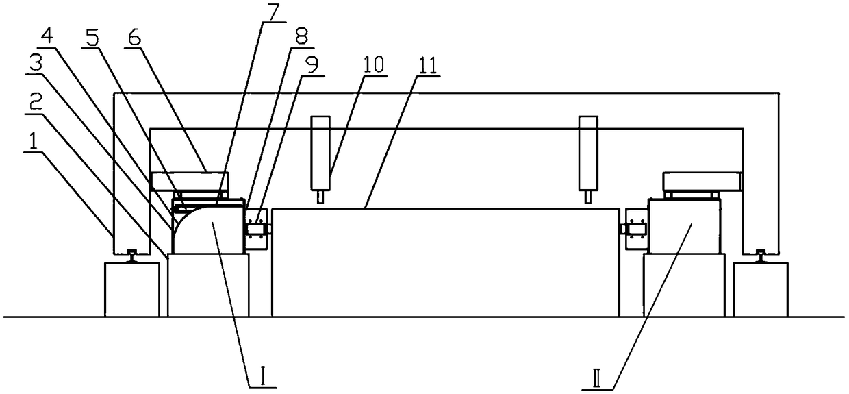
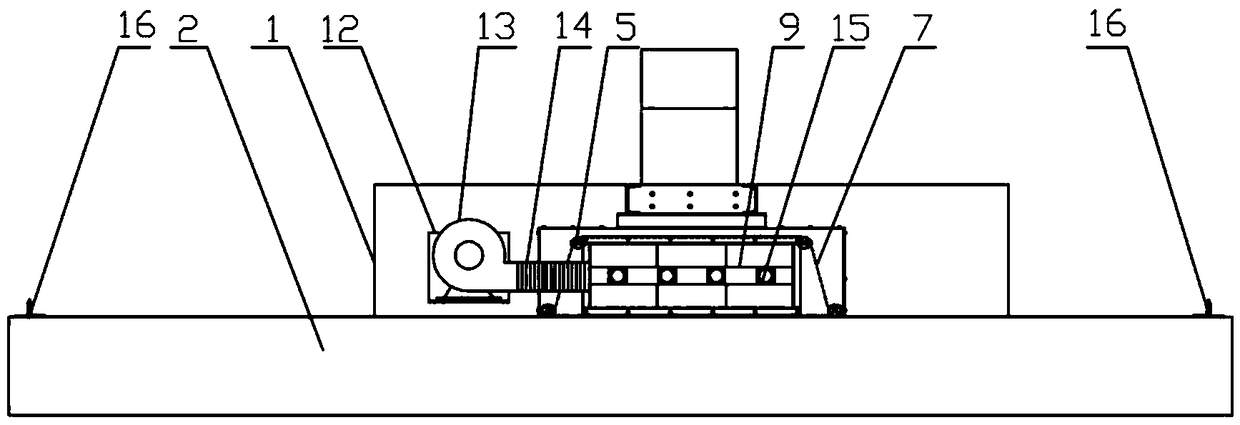
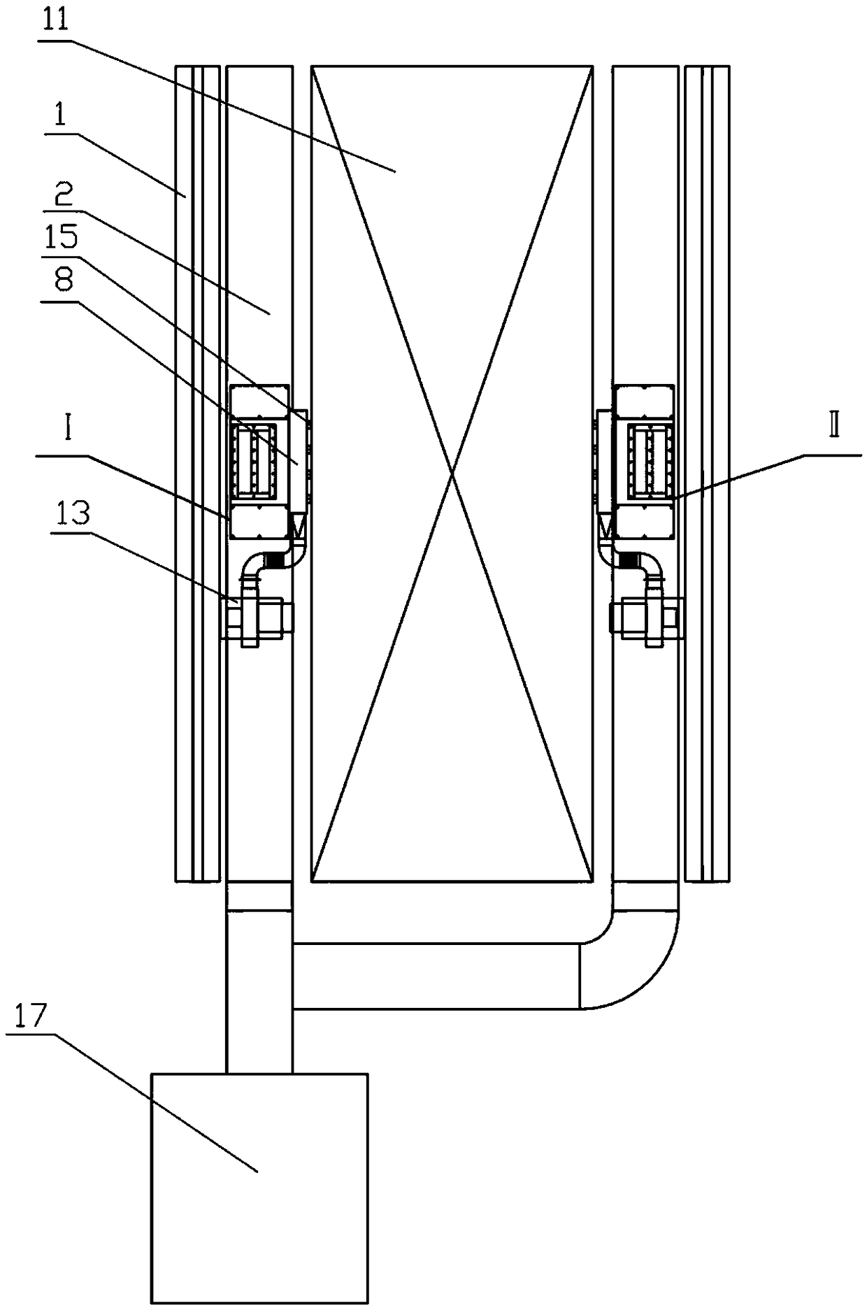
[0023] Such as Figure 1 to Figure 3 As shown, a slidable smoke trapping and blowing device includes two smoke trapping and blowing mechanisms AI and smoke trapping blowing mechanisms BII with the same structure and oppositely arranged, each smoke trapping and blowing mechanism includes a housing 3, a blower 13 , blowing pipe 9, smoking hood 8 and blowing port 15, the housing 3 is installed on the side beam 1 of the CNC cutting machine through the support frame 6 and can be driven to slide synchronously through the side beam 1 of the cutting machine, and the blower 13 is installed on the CNC cutting machine through the support 12. The side beam 1 of the cutti...


PUM


Abstract

The invention relates to a slidable smoke absorption trapping and blowing device. The slidable smoke absorption trapping and blowing device comprises a smoke absorption trapping and blowing mechanismA and a smoke absorption trapping and blowing mechanism B which are of the same structure and are oppositely arranged. Each smoke absorption trapping and blowing mechanism comprises a shell, a blower,a blowing pipe, a smoke absorption hood and a blowing port. The shells are installed on a side beam of a numerical control cutting machine through support frames and can synchronously slide through the driving of the side beam of the cutting machine. The blowers are installed on the side beam of the numerical control cutting machine through supports and can synchronously slide through the drivingof the side beam of the cutting machine. Each blower is connected with the corresponding blowing pipe through a hose. Each blowing port is fixed in an air outlet of the corresponding blowing pipe. The blowing port of the smoke absorption trapping and blowing mechanism A is matched with the smoke absorption hood of the smoke absorption trapping and blowing mechanism B during use, and the blowing port of the smoke absorption trapping and blowing mechanism B is matched with the smoke absorption hood of the smoke absorption trapping and blowing mechanism A during use. The slidable smoke absorption trapping and blowing device can effectively trap smoke dust, can move synchronously with a cutting torch of the cutting machine and has better dust removal effect when being used together with dustremoval equipment.

Description

technical field [0001] The invention relates to a dust removal device for a numerically controlled cutting machine, in particular to a slidable smoke collecting and blowing device. Background technique [0002] The CNC cutting machine will generate a lot of smoke and dust during the cutting process. These smoke and dust will generally spread around due to the cutting force, which will not only affect the health of the cutting operator, but also adversely affect the normal progress of the cutting process. Therefore, it is necessary to This part of the smoke and dust is collected and then removed by dust removal equipment. However, in the existing dust removal and smoking devices of CNC cutting machines, most of them do not have the function of blowing. When the cutting span exceeds a certain range and the cutting torch is far away from the smoking device, the smoking function gradually attenuates, and the smoke cannot be completely captured and diffused into the working envir...

Claims


Application Information

Patent Timeline
Patent Type & Authority Applications(China)
IPC IPC(8): B23Q11/00B08B15/00
CPCB08B15/007B23Q11/006
Inventor 刘品王玉成
Owner WELLDONE ENVIRONMENTAL PROTECTION EQUIP CHANGSHA
Features
  • R&D
  • Intellectual Property
  • Life Sciences
  • Materials
  • Tech Scout
  • Unparalleled Data Quality
  • Higher Quality Content
  • 60% Fewer Hallucinations
Learn More