A touch display panel and a binding method

A technology of touch display panel and display panel, which is applied in the direction of instruments, electrical digital data processing, and input/output process of data processing, etc., to achieve the effect of realizing narrow frame design, reducing process time cost, and improving reliability

Active Publication Date: 2019-03-08
WUHAN CHINA STAR OPTOELECTRONICS SEMICON DISPLAY TECH CO LTD
View PDF5 Cites 26 Cited by
  • Summary
  • Abstract
  • Description
  • Claims
  • Application Information

AI Technical Summary

Problems solved by technology

Now with the rise of full screens, the requirements for the borders of touch display screens are getting narrower and narrower. However, due to production yield and design considerations, ultra-narrow borders or even borderless borders have always been a bottleneck for touch display screens.

Method used


Image

  • A touch display panel and a binding method
  • A touch display panel and a binding method
  • A touch display panel and a binding method

Examples


Embodiment Construction

[0027] The following descriptions of the various embodiments refer to the accompanying drawings to illustrate specific embodiments that the present application can be used to implement. The directional terms mentioned in this application, such as [top], [bottom], [front], [back], [left], [right], [inside], [outside], [side], etc., are for reference only The orientation of the attached schema. Therefore, the directional terms used are used to illustrate and understand the application, but not to limit the application. In the figures, structurally similar elements are denoted by the same reference numerals.

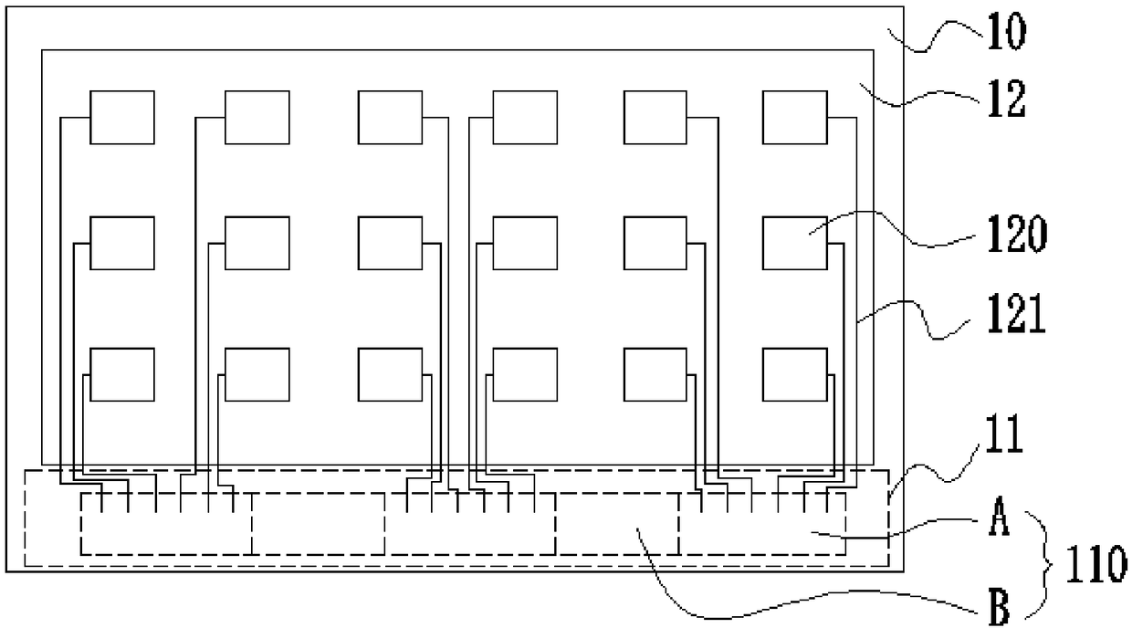
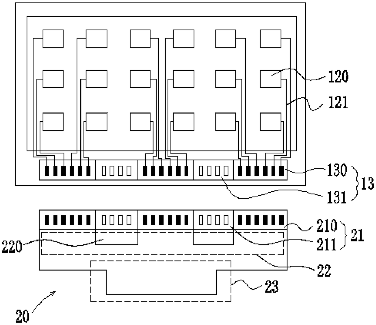
[0028] This application is aimed at the technical problems of the touch display panel in the prior art, the bonding process of the flexible printed circuit board with multi-segment pads is high in time and cost, and the reliability is low, which is not conducive to the realization of the narrow frame design of the touch display panel. This embodiment can solve this defect...


PUM


Abstract

The invention provides a touch display panel and a binding method. The touch display panel comprises a display panel, wherein a binding area is arranged corresponding to a non-display area, and the binding area comprises a conductive bonding area arranged in segments and a non-conductive bonding area located between two adjacent conductive bonding areas; a touch layer prepared on the display panel, comprising an inductive electrode and a signal lead electrically connected to the inductive electrode, the other end of the signal lead extending to the conductive bonding region; a flexible printedcircuit board including a first pad corresponding to the binding region, wherein the first pad includes a first connection sub-pad corresponding to the conductive bonding region and a first dummy sub-pad corresponding to the non-conductive bonding region, and the first connection sub-pad is used for electrical connection with the signal lead.

Description

technical field [0001] The present application relates to the field of display technology, in particular to a touch display panel and a binding method. Background technique [0002] Touch is currently the simplest and most convenient way of human-computer interaction, so touch screens are more and more applied to various electronic products. Capacitive touch screens include surface capacitive and transmissive capacitive, and transmissive capacitive can be further divided into self-capacitive and mutual capacitive. Now with the rise of full screens, the requirements for touch display screen borders are getting narrower and narrower. However, due to production yield and design considerations, ultra-narrow borders or even borderless borders have always been a bottleneck for touch display screens. [0003] Therefore, there are defects in the prior art, and improvement is badly needed. Contents of the invention [0004] The present application provides a touch display panel a...

Claims


Application Information

Patent Timeline
Patent Type & Authority Applications(China)
IPC IPC(8): G06F3/044
CPCG06F3/044G06F3/04164G06F3/0443G06F2203/04103
Inventor 刘敏伦戴其兵林丹
Owner WUHAN CHINA STAR OPTOELECTRONICS SEMICON DISPLAY TECH CO LTD
Why Eureka
Try Eureka