Structure-optimized switch cabinet

A switchgear and cabinet technology, applied in the field of switchgear, can solve the problems affecting the conductive contact of the common knife 6', the deformation of the common knife 6', and the lack of a limit structure, so as to avoid serious deformation of the knife and copper bars. bad contact effect

Inactive Publication Date: 2019-03-08
王赛
View PDF0 Cites 0 Cited by
  • Summary
  • Abstract
  • Description
  • Claims
  • Application Information

AI Technical Summary

Problems solved by technology

[0002] At present, general switch cabinets such as figure 1 As shown, the switch cabinet includes a cabinet body 1, and multiple sets of switch knife assemblies are arranged in the cabinet body 1. Each set of switch knife assemblies is composed of a copper bar 3 and a common switch knife 6'. One side wall of the cabinet body 1 A horizontal insulating sleeve 2 is plugged and fixed, and a horizontal copper bar 3 is plugged into the insulating sleeve 2. The inner end of the copper bar 3 is inserted into the cabinet body 1, and the outer end is exposed outside the cabinet body 1. The inner end of the copper bar 3 The cabinet body 1 on the end side is equipped with a reversible ordinary switch knife 6', the ordinary switch knife 6' is hinged on the first insulator 4', the inner end of the copper bar 3 is fixed on the second insulator 5', and the first insulator 4' and the second insulator 5' are fixed in the cabinet body 1, the first connecting rod 9' is hinged on the ordinary switch blade 6', the lower end of the first connecting rod 9' is hinged on the second connecting rod 8', the second connecting rod The end sleeve of the rod 8' is fixed on the operating shaft 7'; the current switch cabinet knife assembly does not have an effective limit structure, and when the operating shaft 7' rotates too much, it is easy to cause deformation of the ordinary knife 6'. When the switch knife 6' is too deformed, it will affect the conductive contact between the ordinary switch knife 6' and the copper bar 3

Method used


Image

  • Structure-optimized switch cabinet
  • Structure-optimized switch cabinet

Examples


Embodiment

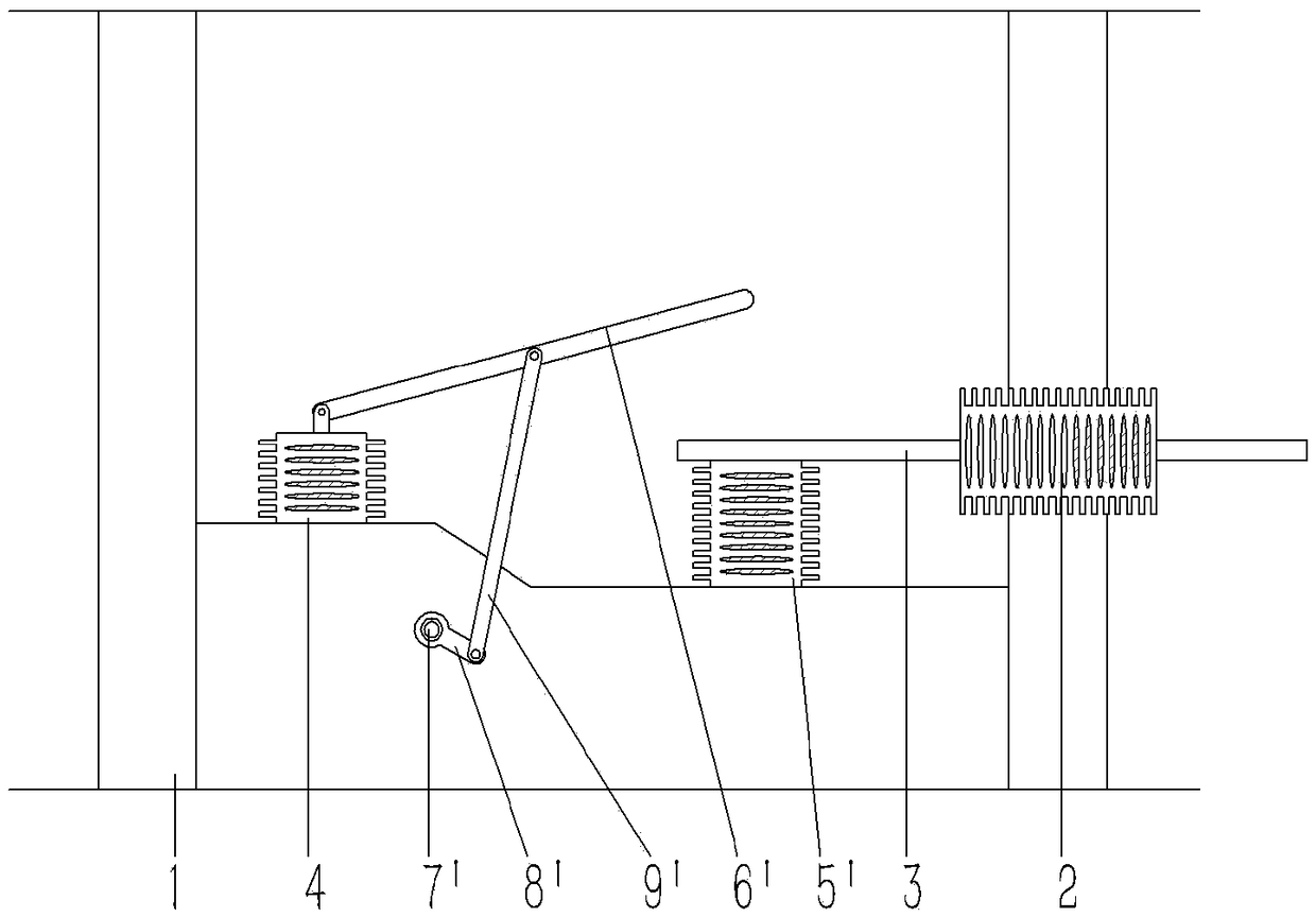
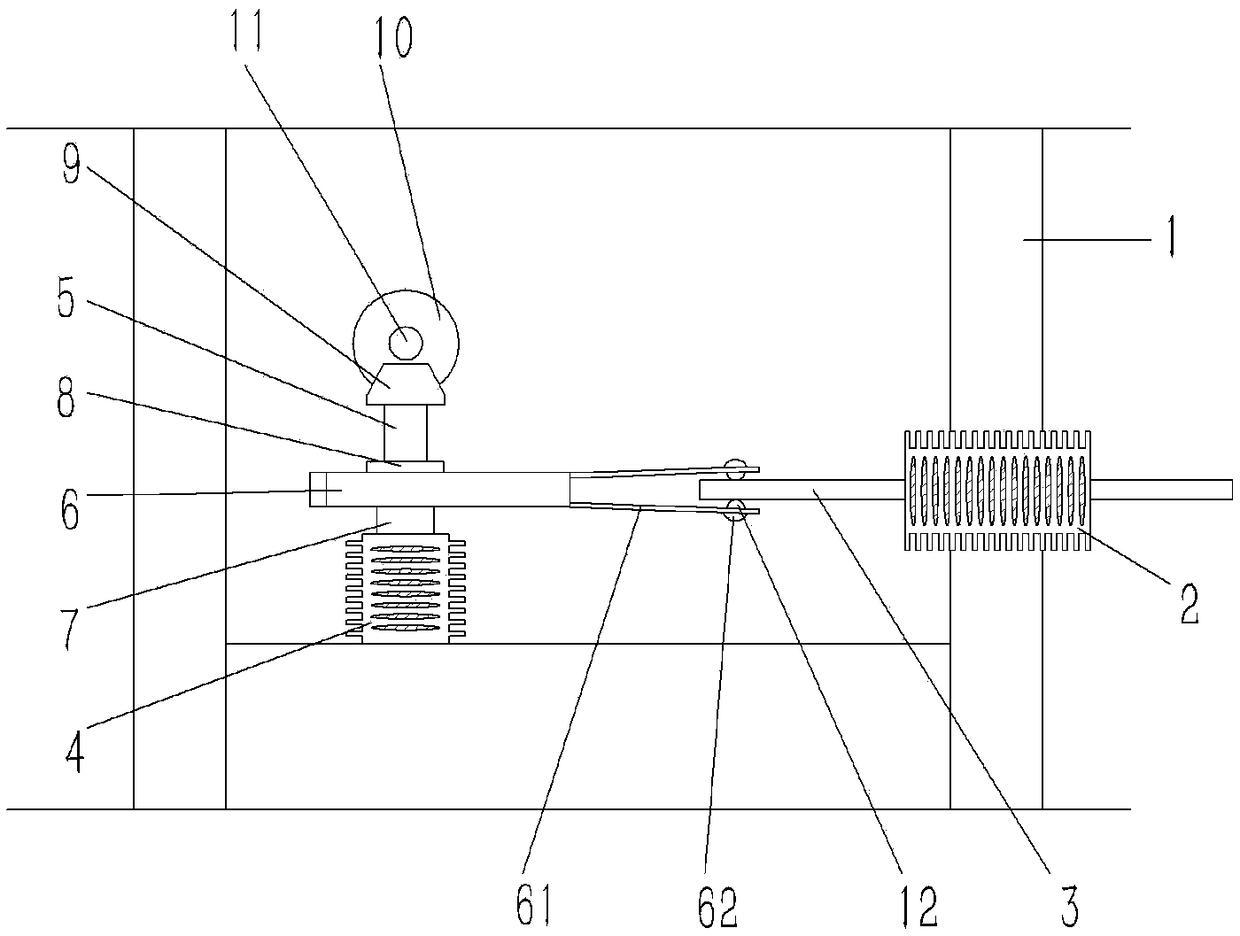
[0015] Example: see figure 2 As shown, a switch cabinet with an optimized structure includes a cabinet body 1 of the switch cabinet. Several groups of switch knife assemblies are arranged in the cabinet body 1. The switch knife components are composed of copper bars 3 and special-shaped switch knives 6. The cabinet body 1 A horizontal insulating sleeve 2 is plugged and fixed on one side of the side wall, and a horizontal copper bar 3 is inserted in the insulating sleeve 2. One end of the copper bar 3 is inserted in the cabinet body 1, and the other end is exposed outside the cabinet body 1. The cabinet body A special-shaped gate knife 6 opposite to the copper bar 3 is inserted in the body 1. The end of the special-shaped gate knife 6 close to the copper bar 3 is formed with two elastic contact pieces 61, and the two ends of the elastic contact piece 61 are elastically against the On the upper and lower end faces of the copper bar 3, the other end of the special-shaped switch ...


PUM


Abstract

The invention discloses a structure-optimized switch cabinet. The structure-optimized switch cabinet comprises a cabinet body of the switch cabinet, wherein multiple groups of knife switch assembliesare arranged in the cabinet body, a horizontal insulation sleeve is fixedly inserted into a side wall of one side of the cabinet body, a horizontal copper bar is inserted into the insulation sleeve, one end of the copper bar is inserted into the cabinet body, the other end of the copper bar is exposed out of an outer side of the cabinet body, an irregularly-shaped knife switch is inserted into thecabinet body and is opposite to the copper bar, an upper elastic contact piece and a lower elastic contact piece are formed in one end, near to the copper bar, of the irregularly-shaped knife switch,two ends of the elastic contact pieces elastically prop against an upper end surface and a lower end surface of the copper bar, the other end of the irregularly-shaped knife switch is fixedly inserted to a vertical support shaft, a lower end of the support shaft is hinged with a first insulator, the first insulator is fixed in the cabinet, a driven bevel gear is fixedly inserted to an upper end surface, extending out of the irregularly-shaped knife switch, of an upper end of the support shaft, a driving bevel gear is engaged with the driven bevel gear, a driving shaft is fixedly inserted to the driving bevel gear, and two ends of the driving shaft are hinged with the cabinet body. By the structure-optimized switch cabinet, the situation that the knife switch is seriously deformed and is unfavorably contacted with the copper bar in the prior art is prevented.

Description

Technical field: [0001] The invention relates to the technical field of electrical products, and more specifically relates to a structurally optimized switchgear. Background technique: [0002] At present, general switch cabinets such as figure 1 As shown, the switch cabinet includes a cabinet body 1, and multiple sets of switch knife assemblies are arranged in the cabinet body 1. Each set of switch knife assemblies is composed of a copper bar 3 and a common switch knife 6'. One side wall of the cabinet body 1 A horizontal insulating sleeve 2 is plugged and fixed, and a horizontal copper bar 3 is plugged into the insulating sleeve 2. The inner end of the copper bar 3 is inserted into the cabinet body 1, and the outer end is exposed outside the cabinet body 1. The inner end of the copper bar 3 The cabinet body 1 on the end side is equipped with a reversible ordinary switch knife 6', the ordinary switch knife 6' is hinged on the first insulator 4', the inner end of the copper...

Claims


Application Information

Patent Timeline
Patent Type & Authority Applications(China)
IPC IPC(8): H01H21/56H01H21/36H02B1/32
CPCH01H21/56H01H21/36H02B1/32
Inventor 王赛
Owner 王赛
Why Eureka
Try Eureka