
Feed inlet with improved structure on smelting furnace
A technology for smelting furnaces and feed ports, applied in the field of smelting furnaces, can solve the problems of high labor intensity, endangering the health of personnel, and inability to stay for a long time, so as to achieve the effect of easy cleaning and reducing coking
- Summary
- Abstract
- Description
- Claims
- Application Information
AI Technical Summary
Problems solved by technology
Method used
Image

Examples
Embodiment
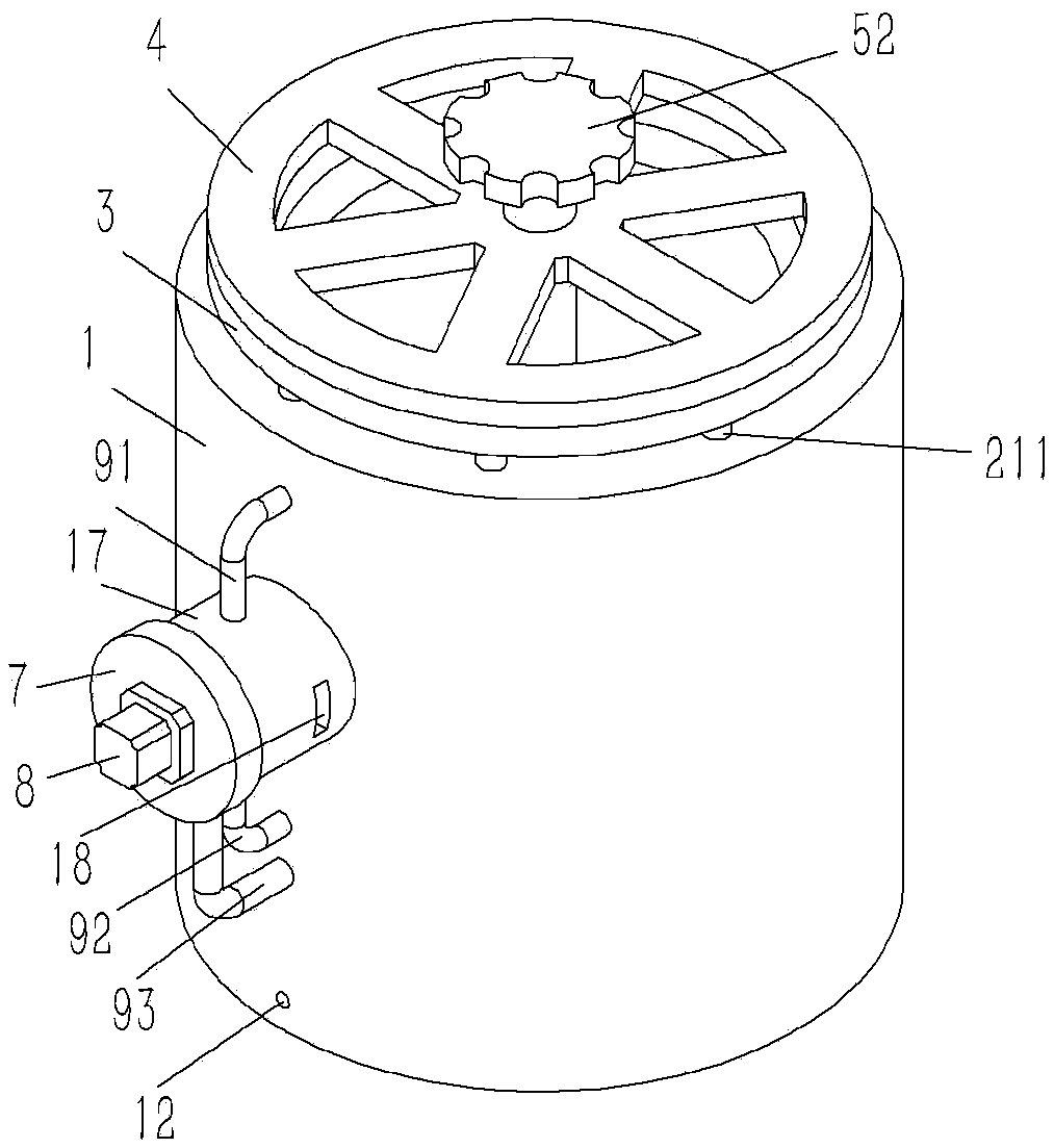
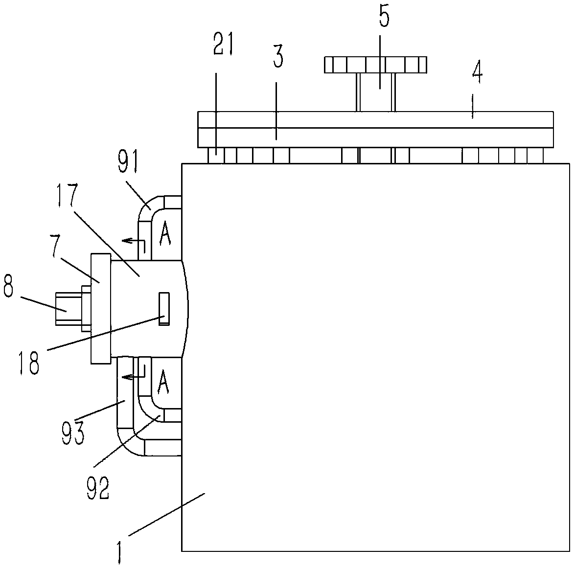
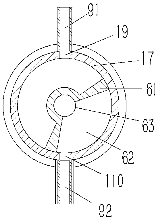
[0019] Example: see figure 1 As shown, a feed port with an improved structure on a smelting furnace includes a feed pipe 1, the lower end of the feed pipe 1 is formed with a water tank chamber 11, and the outer wall of the lower end of the feed pipe 1 is formed with a water tank chamber 11. The water injection hole 12, the feed pipe 1 on the upper side of the water tank cavity 11 is formed with a vertical annular cavity 13, and the upper and lower bottom surfaces of the annular cavity 13 are formed with annular cutouts 14, and the upper and lower ends of the annular cavity 13 are The first air hole 15 and the second air hole 16 that penetrate the outer wall of the feed pipe 1 are respectively formed on the side wall of the cut groove 14, and the outer wall of the feed pipe 1 between the first air hole 15 and the second air hole 16 is formed There is an annular boss 17, and a circular rotating disk 6 is inserted into the annular boss 17. A fan-shaped stopper 61 is formed on the...
PUM
 Abstract
Description
Claims
Application Information