Structurally optimized feeding port on smelting furnace

A technology for smelting furnaces and feeding ports, applied in the field of smelting furnaces, can solve the problems of high labor intensity, endangering the health of personnel, and inability to stay for a long time, so as to achieve the effect of easy cleaning and reducing coking

Inactive Publication Date: 2020-10-30
陈 文清
View PDF0 Cites 0 Cited by
  • Summary
  • Abstract
  • Description
  • Claims
  • Application Information

AI Technical Summary

Problems solved by technology

[0002] Metallurgy furnace is a commonly used metallurgical industrial equipment. When feeding into the metallurgy furnace, the furnace material will stick to the inlet of the metallurgy furnace and coke. The existing coking problem in the inlet of the metallurgical furnace is generally manually stabbed. The labor intensity required is high, and there are many people
If the furnace charge contains substances that are difficult to clean, once it sticks to the charging port, it will not help even manual poking. In addition, sometimes a large amount of smoke will be emitted when the furnace charge is stuck on the charging port, which will endanger the health of personnel and cause personnel to operate the table. Can't stay on for a long time

Method used


Image

  • Structurally optimized feeding port on smelting furnace

Examples


Embodiment

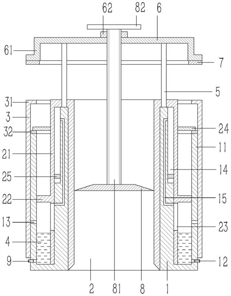
[0018] Example: see figure 1 As shown, a structure-optimized feeding port on a smelting furnace includes a feeding conduit 1, an annular water tank 11 is formed on the outer wall of the lower end of the feeding conduit 1, and a penetrating feeding conduit is formed on the inner wall of the upper end of the water tank 11 near the side of the feeding conduit 1 1 An annular groove 14 on the upper end surface; the feeding conduit 1 is inserted with a movable pipe fitting 2, the upper end of the movable pipe fitting 2 is formed with a flange, and the outer side of the movable pipe fitting 2 flange is planned to form an annular inner valve plate 21 , the lower end of the inner valve plate 21 is plugged into the water tank 11 of the feeding conduit 1, an annular sealing ring 22 is formed on the outer wall of the inner valve plate 21, and the sealing ring 22 abuts against the inner wall of the water tank 11 away from the feeding conduit 1 and Located in the middle of the water tank 11...


PUM


Abstract

The invention discloses a structurally optimized feeding port on a smelting furnace. The structurally optimized feeding port comprises a feeding guide pipe, an annular water groove is formed in the outer wall of the lower end of the feeding guide pipe, and an annular slot penetrating the upper end face of the feeding guide pipe is formed in the inner wall of the side, close to the feeding guide pipe, of the upper end of the water groove. A movable pipe is inserted into the feeding guide pipe, a flange is formed at the upper end of the movable pipe, an annular inner valve plate is planned and formed on the outer side of the flange of the movable pipe, and the lower end of the inner valve plate is inserted into the water groove of the feeding guide pipe. An annular sealing ring is formed onthe outer wall of the inner valve plate, the sealing ring abuts against the inner side wall, away from the feeding guide pipe, of the water groove and is located in the middle of the water groove, a water injection opening is formed in the lower end of the water groove, and pressure relief holes communicating with an inner cavity of the water groove are formed in the position, on the upper side ofthe water injection opening, of the outer wall of the water groove. A ventilating slot is formed in the position, on the lower side of the sealing ring, of the inner valve plate, and a ventilating hole channel communicating with the annular slot is formed in the position, at the upper end of the ventilating slot, of the inner wall of the water groove.

Description

Technical field: [0001] The invention relates to the technical field of smelting furnaces, in particular to a structure-optimized feeding port on the smelting furnace. Background technique: [0002] Metallurgy furnace is a commonly used metallurgical industrial equipment. When feeding into the metallurgy furnace, the furnace material will stick to the inlet of the metallurgy furnace and coke. The existing coking problem in the inlet of the metallurgical furnace is generally manually stabbed. The required labor intensity is relatively large and there are many people. If the furnace charge contains substances that are difficult to clean, once it sticks to the charging port, it will not help even manual poking. In addition, sometimes a large amount of smoke will be emitted when the furnace charge is stuck on the charging port, which will endanger the health of personnel and cause personnel to operate the table. Unable to stay on for a long time. Invention content: [0003] ...

Claims


Application Information

Patent Timeline
Patent Type & Authority Applications(China)
IPC IPC(8): F27D3/00F27D9/00
CPCF27D3/0084F27D9/00F27D2009/0013
Inventor 陈文清
Owner 陈 文清
Why Eureka
Try Eureka