Cable laying support

A cable laying and cable technology, applied in the field of cable laying brackets, can solve problems such as steel armor cut, cable protection pipe drop, cable sheath damage, etc., to avoid damage and ensure integrity.

Inactive Publication Date: 2019-03-08
STATE GRID CORP OF CHINA +2
View PDF8 Cites 2 Cited by
  • Summary
  • Abstract
  • Description
  • Claims
  • Application Information

AI Technical Summary

Problems solved by technology

[0003] The purpose of the present invention is to provide a cable laying bracket, which aims to solve the problem that when the cable is pulled, the cable sheath is damaged or even the steel armor is broken due to the turning angle in the laying path and the drop of the cable protection tube.

Method used


Image

  • Cable laying support
  • Cable laying support
  • Cable laying support

Examples


Embodiment Construction

[0040] In order to make the technical problems, technical solutions and beneficial effects to be solved by the present invention clearer, the present invention will be further described in detail below in conjunction with the accompanying drawings and embodiments. It should be understood that the specific embodiments described here are only used to explain the present invention, not to limit the present invention.

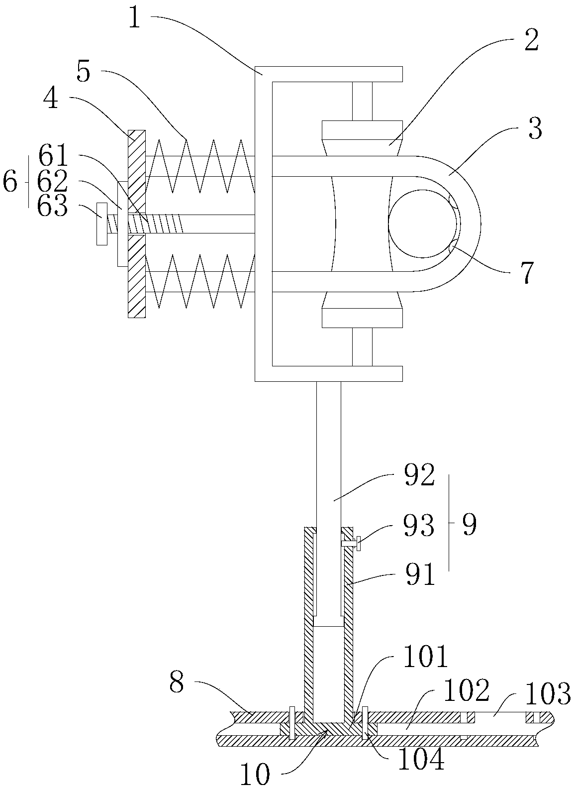
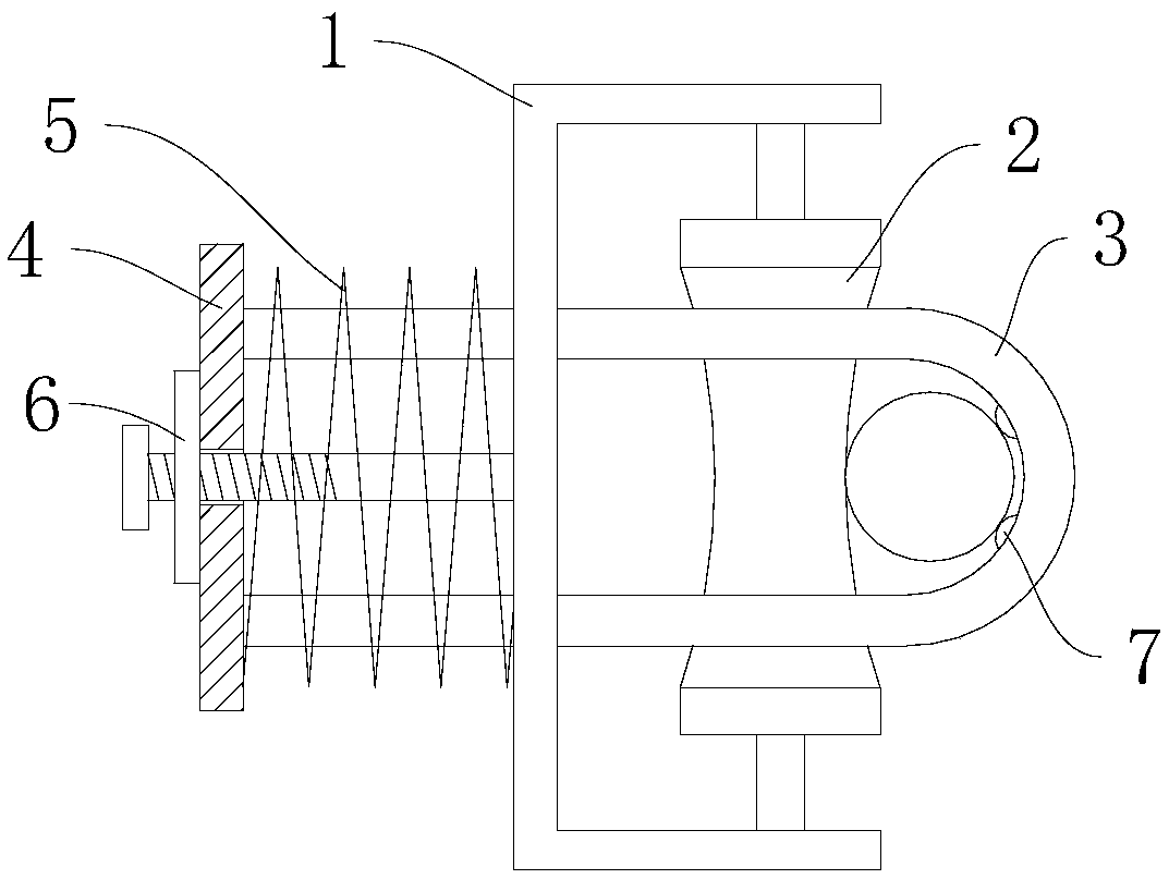
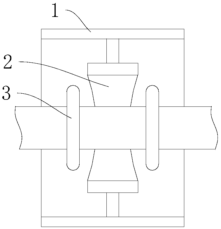
[0041] The cable laying bracket provided by the present invention will now be described. see Figure 1 to Figure 3 , Cable laying bracket, including bracket 1, sliding roller 2, snap ring 3, pressure plate 4, spring 5 and adjustment assembly 6.

[0042] Bracket 1; the sliding roller 2 is rotatably arranged on the bracket 1; the snap ring 3 is a U-shaped structure, two in number, arranged on both sides of the sliding roller 2, the closed end is located in the bracket 1, and the free end runs through the bracket 1. The closed end of a snap ring 3 abuts the cable on...


PUM


Abstract

The invention provides a cable laying support, and belongs to the technical field of power equipment. The cable laying support comprises a support body, a sliding roller, clamping rings, a pressing plate, a spring and an adjusting assembly. The sliding roller is arranged on the support body in a rotatable mode; the two clamping rings are of U-shaped structures and are arranged on the two sides ofthe sliding roller, the closed ends are located in the support body, the free ends penetrate through the support body, and the closed ends of the two clamping rings enable a cable to be abutted to a side surface of the sliding roller; the pressing plate is arranged on one side of the support body and is connected with the free ends of the clamping rings; the spring sleeves the free ends of the clamping rings and is tightly pressed between the pressing plate and the support body; and the adjusting assembly is used for adjusting the distance between the pressing plate and the support body. According to the cable laying support provided by the invention, the cable penetrates through the two clamping rings; the clamping rings on the two sides of the sliding roller are adjusted through the adjusting assembly; the closed ends of the two clamping rings enable the cable to be abutted to the outer surface of the sliding roller; and during cable laying, the situations that a cable sheath is damaged and a steel armor is broken are avoided, and the integrity of the cable is guaranteed.

Description

technical field [0001] The invention belongs to the technical field of electric equipment, and more specifically relates to a cable laying bracket. Background technique [0002] In the power construction of the urban distribution network, it is necessary to carry out the construction of distribution network projects, community facilities and other construction power cables into the ground. When the cables are laid, the cable laying path will turn corners and the drop between the cable protection tubes will be large. When the cable is pulled, it will cause damage to the cable sheath, and what is more, the steel armor will be cut, resulting in a decrease in the insulation strength of the cable, and the cable is scrapped, which affects the construction progress and quality. Contents of the invention [0003] The purpose of the present invention is to provide a cable laying bracket, which aims to solve the problem of cable sheath damage or even steel armor being cut when the c...

Claims


Application Information

Patent Timeline
Patent Type & Authority Applications(China)
IPC IPC(8): H02G1/06
CPCH02G1/06
Inventor 阎立乾朱丽平朱智博李金辉
Owner STATE GRID CORP OF CHINA
Why Eureka
Try Eureka