Intelligent shared charging base station of mobile phone

A technology for charging base stations and mobile phones, which is applied to charging stations for mobile devices, electric vehicle charging technology, and current collectors. Detection of maintenance costs and the effect of ease of use

Inactive Publication Date: 2019-03-08
王艳
View PDF0 Cites 4 Cited by
  • Summary
  • Abstract
  • Description
  • Claims
  • Application Information

AI Technical Summary

Problems solved by technology

[0002] Nowadays, mobile phones have become a necessity in people's lives. When traveling outside, mobile phones facilitate users' long-distance communication on the one hand, and on the other hand, they are used for users' daily entertainment. And when using a mobile phone, it will be very embarrassing for us if the mobile phone is out of power. In order to solve this dilemma, some charging interfaces have also appeared in major public places, such as bus stations, railway stations, large supermarkets, chain fast food restaurants and some Entertainment places, etc., so that the user can replenish the power at any time, this setting is indeed convenient for the user's life, but at present, the existing mobile phone charging station on the market includes a charging box and a charging interface arranged outside the charging box. The charging interface is exposed on the The outside of the charging box and public places are relatively messy due to the messy people, which can easily cause damage to the charging interface during use, which seriously affects the service life of the charging interface. Therefore, a mobile phone with ingenious structure, simple principle and convenient use Intelligent shared charging base station is very important

Method used


Image

  • Intelligent shared charging base station of mobile phone
  • Intelligent shared charging base station of mobile phone
  • Intelligent shared charging base station of mobile phone

Examples


Embodiment Construction

[0049] The technical solutions in the embodiments of the present invention will be clearly and completely described below in conjunction with the accompanying drawings in the embodiments of the present invention. Obviously, the described embodiments are only some, not all, embodiments of the present invention. Based on the embodiments of the present invention, all other embodiments obtained by persons of ordinary skill in the art without making creative efforts belong to the protection scope of the present invention.

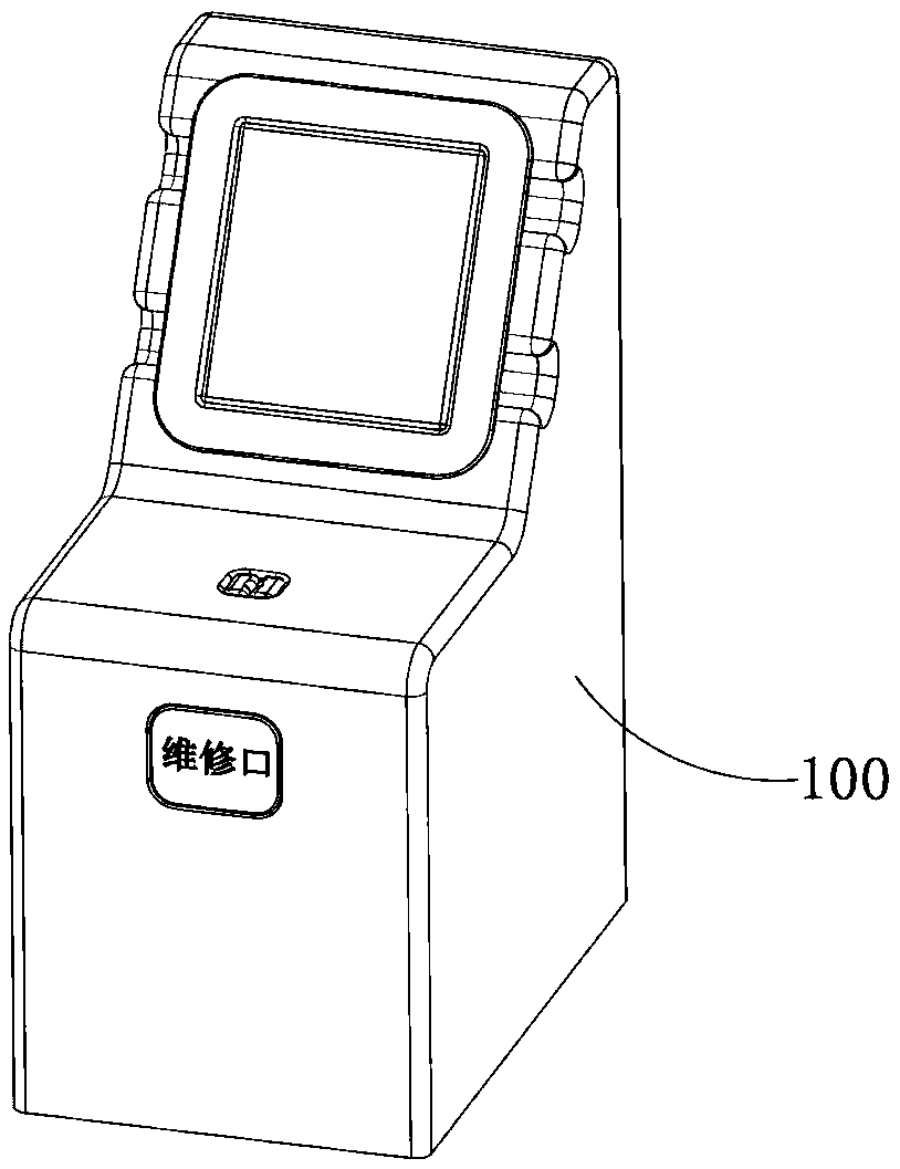
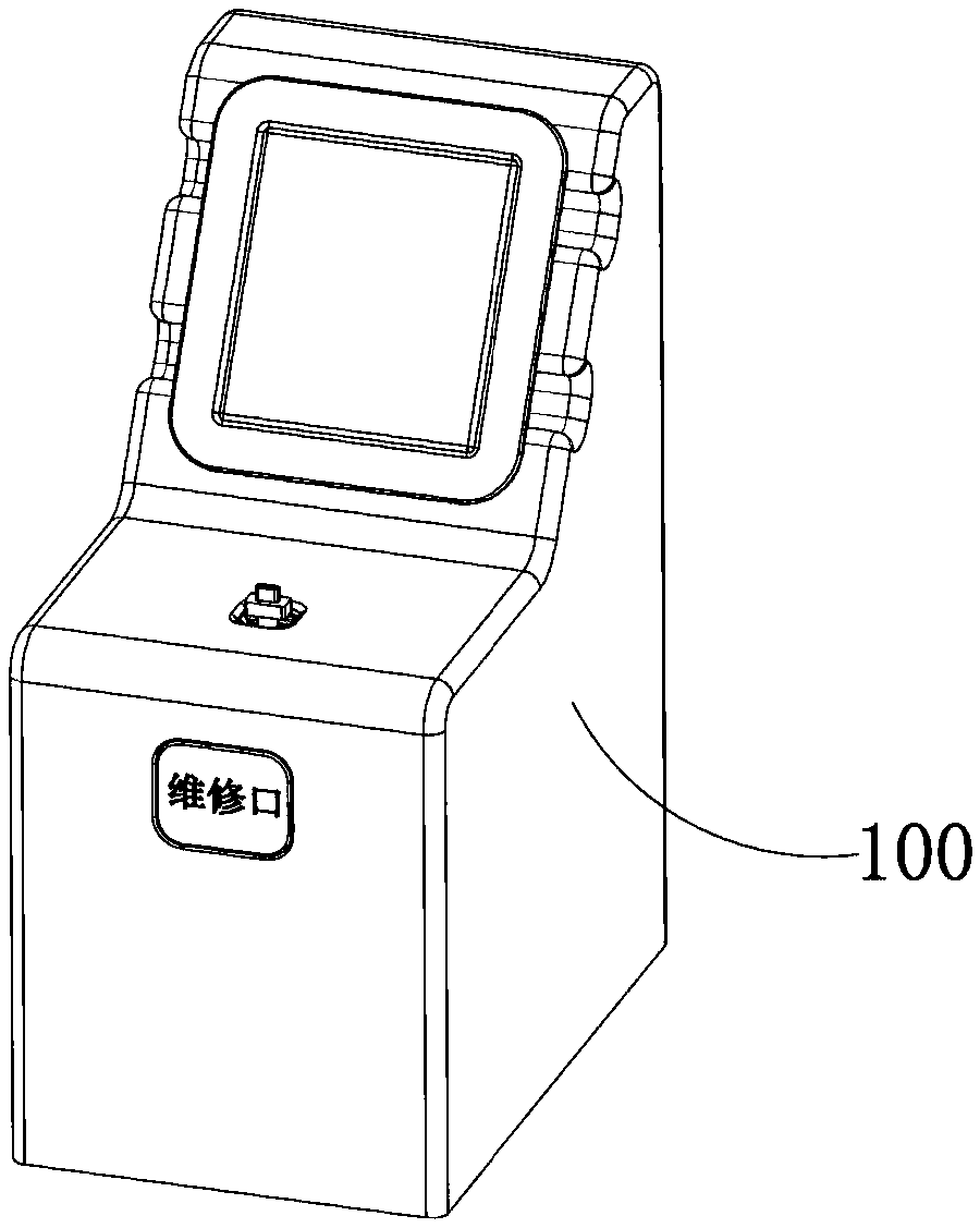
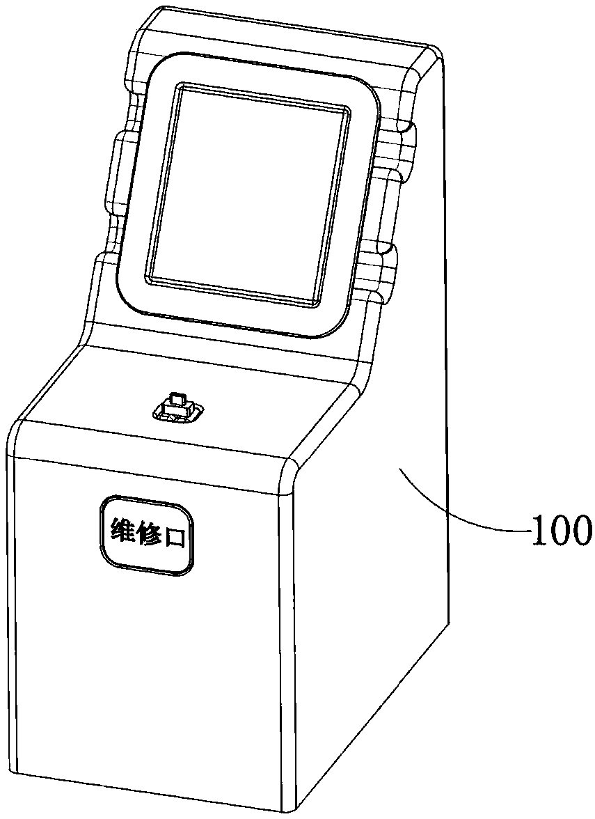
[0050] see Figure 1-27 , a concealed mobile phone charging station applied in public places, which includes a charging box 100 for charging mobile phones. The charging box 100 includes a rectangular and vertically arranged box body 101, and an opening 102 is provided on the upper end of the box body 101. The opening of the opening 102 is provided with a shielding door member 110 for shielding and blocking it, and a charging plug member 120 is arranged in the bo...


PUM


Abstract

The invention provides an intelligent shared charging base station of a mobile phone. The intelligent shared charging base station comprises a charging box, wherein the charging box comprises a box body, and an opening is formed in the box body; a shielding door component used for shielding and blocking the opening is arranged at the opening; a charging plug component which is movably arranged isarranged in the box body; a power driving device used for driving the shielding door component to be mutually switched between an open state and a shielding state or driving the charging plug component to be mutually switched between an extending state and a retraction state is arranged in the box body; a shielding transmission mechanism is arranged between the power driving device and the shielding door component, and a lifting control mechanism is arranged between the power driving device and the charging plug component; a controller used for controlling the running process of the power driving device is further arranged in the box body; the shielding door component comprises two shielding doors which are movably arranged, wherein the two shielding doors are symmetrically arranged in theopening direction of the opening; and the two shielding doors are matched with each other and are matched with the opening and are used for shielding and plugging the opening.

Description

technical field [0001] The invention relates to a mobile phone charging station, in particular to an intelligent shared charging base station for mobile phones. Background technique [0002] Nowadays, mobile phones have become a necessity in people's lives. When traveling outside, mobile phones facilitate users' long-distance communication on the one hand, and on the other hand, they are used for users' daily entertainment. And when using a mobile phone, it will be very embarrassing for us if the mobile phone is out of power. In order to solve this dilemma, some charging interfaces have also appeared in major public places, such as bus stations, railway stations, large supermarkets, chain fast food restaurants and some Entertainment places, etc., so that the user can replenish the power at any time, this setting is indeed convenient for the user's life, but at present, the existing mobile phone charging station on the market includes a charging box and a charging interface a...

Claims


Application Information

Patent Timeline
Patent Type & Authority Applications(China)
IPC IPC(8): H02J7/00G07F15/00
CPCG07F15/006H02J7/0027H02J7/0042Y02T90/12
Inventor 不公告发明人
Owner 王艳
Why Eureka
Try Eureka