
Dynamic Balance Structure of Excitation Rotor and Synchronous Generator

A technology for synchronous generators and exciting rotors, applied in synchronous generators, magnetic circuit rotating parts, magnetic circuit shape/style/structure, etc. Throwing out and other problems to achieve the effect of alleviating cumbersome procedures, simple structure and convenient operation

Active Publication Date: 2020-11-17
WUXI FARADAY ALTERNATORS
View PDF7 Cites 0 Cited by
  • Summary
  • Abstract
  • Description
  • Claims
  • Application Information

AI Technical Summary

Problems solved by technology

[0005] The purpose of the present invention is to provide an excitation rotor dynamic balance structure and a synchronous generator to alleviate the cumbersome procedures of using dynamic balancing mud in the prior art, resulting in unreliable dynamic balancing mud and the risk of breaking or falling, and There is a technical problem that the filled weight parts are easy to throw out and fall off

Method used


Image

  • Dynamic Balance Structure of Excitation Rotor and Synchronous Generator
  • Dynamic Balance Structure of Excitation Rotor and Synchronous Generator
  • Dynamic Balance Structure of Excitation Rotor and Synchronous Generator

Examples


Embodiment Construction

[0036] In order to make the purpose, technical solutions and advantages of the embodiments of the present invention clearer, the technical solutions in the embodiments of the present invention will be clearly and completely described below in conjunction with the drawings in the embodiments of the present invention. Obviously, the described embodiments It is a part of embodiments of the present invention, but not all embodiments. The components of the embodiments of the invention generally described and illustrated in the figures herein may be arranged and designed in a variety of different configurations.

[0037] Accordingly, the following detailed description of the embodiments of the invention provided in the accompanying drawings is not intended to limit the scope of the claimed invention, but merely represents selected embodiments of the invention. Based on the embodiments of the present invention, all other embodiments obtained by persons of ordinary skill in the art wi...


PUM


Abstract

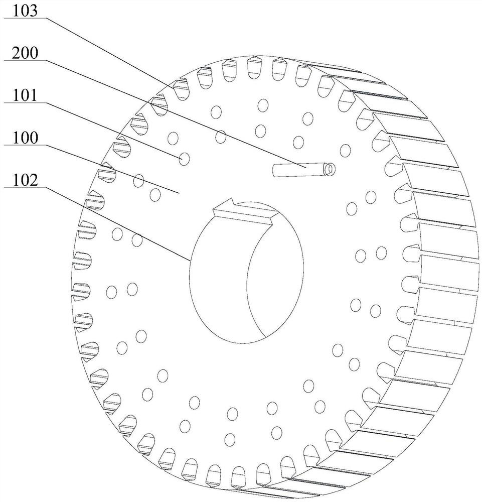
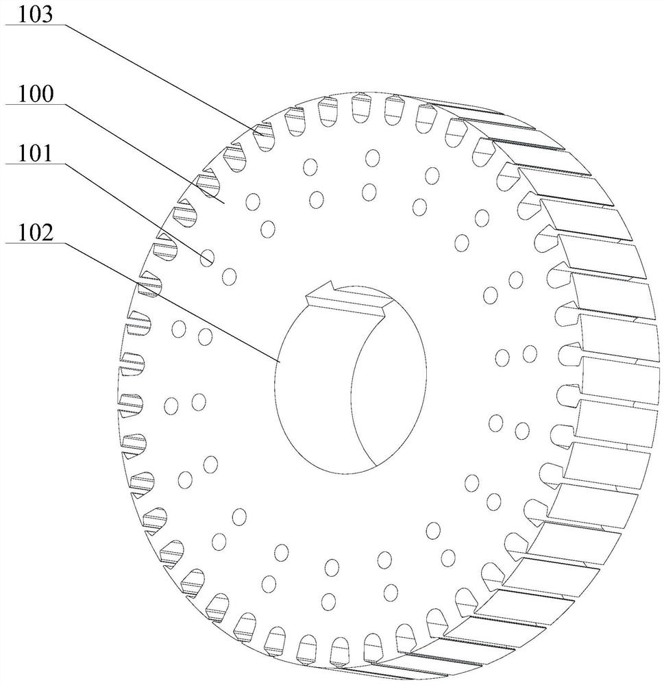
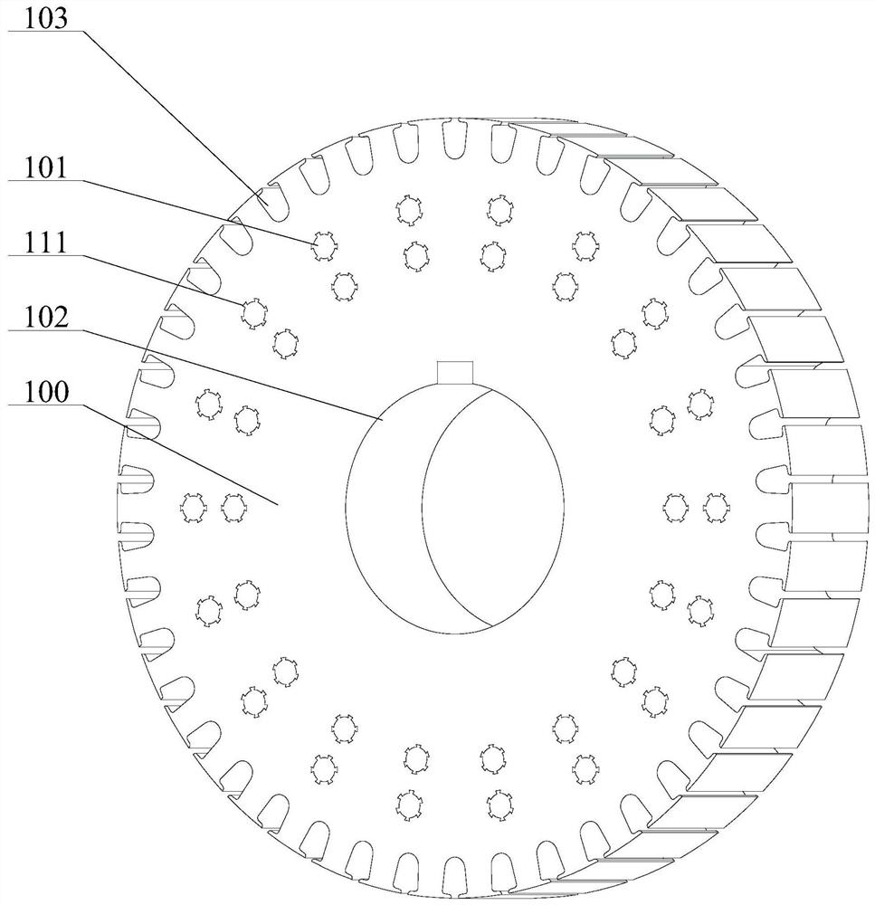
The invention provides an excitation rotor dynamic balancing structure and a synchronous generator and relates to the technical field of motor rotors. The excitation rotor dynamic balancing structurecomprises an excitation rotor punching plate and a dynamic balancing piece; at least two symmetrically arranged placing holes are formed in the excitation rotor punching plate, and the dynamic balancing piece can be contained and fixed in the placing holes; a damping part is arranged on the outer wall, contacted with the placing holes, of the dynamic balancing piece; and by virtue of a mechanicalstructure, the dynamic balancing piece can be fixed in the placing holes of the excitation rotor punching plate, so that balance of the excitation rotor punching plate is corrected, and unbalance of an excitation rotor is eliminated; and by arranging the damping part, stability of the dynamic balancing piece and the placing holes is guaranteed, so that the dynamic balancing piece and the placing holes are more fixed, the technical problems that dynamic balancing mud is unreliable and a risk that the dynamic balancing mud is fractured or falls off can exist as a procedure of using the dynamic balancing mud is complicated in the prior art are alleviated, easy operation, simple structure as well as effectivity, rapidness and convenience are realized, and accurate and low-risk balancing of unbalance amount exceeding the standard is achieved.

Description

technical field [0001] The invention relates to the technical field of motor rotors, in particular to an excitation rotor dynamic balance structure and a synchronous generator. Background technique [0002] A synchronous generator is an alternator whose rotor speed is the same as that of the stator's rotating magnetic field. The rotor of the synchronous generator needs to be balanced. If the rotor balance is not adjusted properly, the generator will vibrate. [0003] In the prior art, for the transmission motor, the weight of the rotor of the motor uses dynamic balance mud. The configuration of the balance mud first needs to carry out a 1:1 ratio of the two components of the balance mud, and then knead and mix them with each other; or in the motor The filling of the weight takes place on the rotor. [0004] However, in the prior art, the balance mud is used for electronic rotor balance, and the mixed dynamic balance mud needs to be used up in a short time, otherwise, it wil...

Claims


Application Information

Patent Timeline
Patent Type & Authority Patents(China)
IPC IPC(8): H02K1/26H02K19/16
CPCH02K1/26H02K19/16H02K2213/03
Inventor 赵伟生傅小波
Owner WUXI FARADAY ALTERNATORS
Learn More