Dedicated hanging rack for shot blasting of cast cylinder block of engine

A technology for engines and cylinders, which is applied in the field of special hangers for shot blasting of engine casting cylinders, and can solve problems such as shot blasting dead angle, difficult cleaning, complex structure of engine casting cylinders, etc.

Pending Publication Date: 2019-03-12
HEFEI JAC CASTING
View PDF0 Cites 0 Cited by
  • Summary
  • Abstract
  • Description
  • Claims
  • Application Information

AI Technical Summary

Problems solved by technology

However, in the current shot blasting machine, in order to ensure continuous production, the engine casting cylinder is usually hung on the hanger, and the hanger can be pulled by the traction belt or the traction chain according to the preset track and moved to the shot blasting room according to the predetermined track. , in order to facilitate traction, the shot blasting machine is usually equipped with a guide groove with an open lower end, and the inner corner of the guide groove is easy to accumulate shot blasting dust, which is not easy to clean
In addition, the cast engine block is hung on the hanger at present, and its position is fixed during the shot blasting process. Although the shot blasting inside the shot blasting chamber is everywhere, due to the complex structure of the engine cast block, the fixed engine cast The cylinder body is easy to have a small part of the shot blasting weak point or shot blasting dead angle. To solve this problem, it usually needs a second shot blasting or prolonging the shot blasting time, which limits the improvement of production efficiency.

Method used


Image

  • Dedicated hanging rack for shot blasting of cast cylinder block of engine
  • Dedicated hanging rack for shot blasting of cast cylinder block of engine
  • Dedicated hanging rack for shot blasting of cast cylinder block of engine

Examples


Embodiment Construction

[0013] In order to make the object, technical solution and advantages of the present invention clearer, the present invention will be further described in detail below in conjunction with the accompanying drawings and embodiments. It should be understood that the specific embodiments described here are only used to explain the present invention, not to limit the present invention.

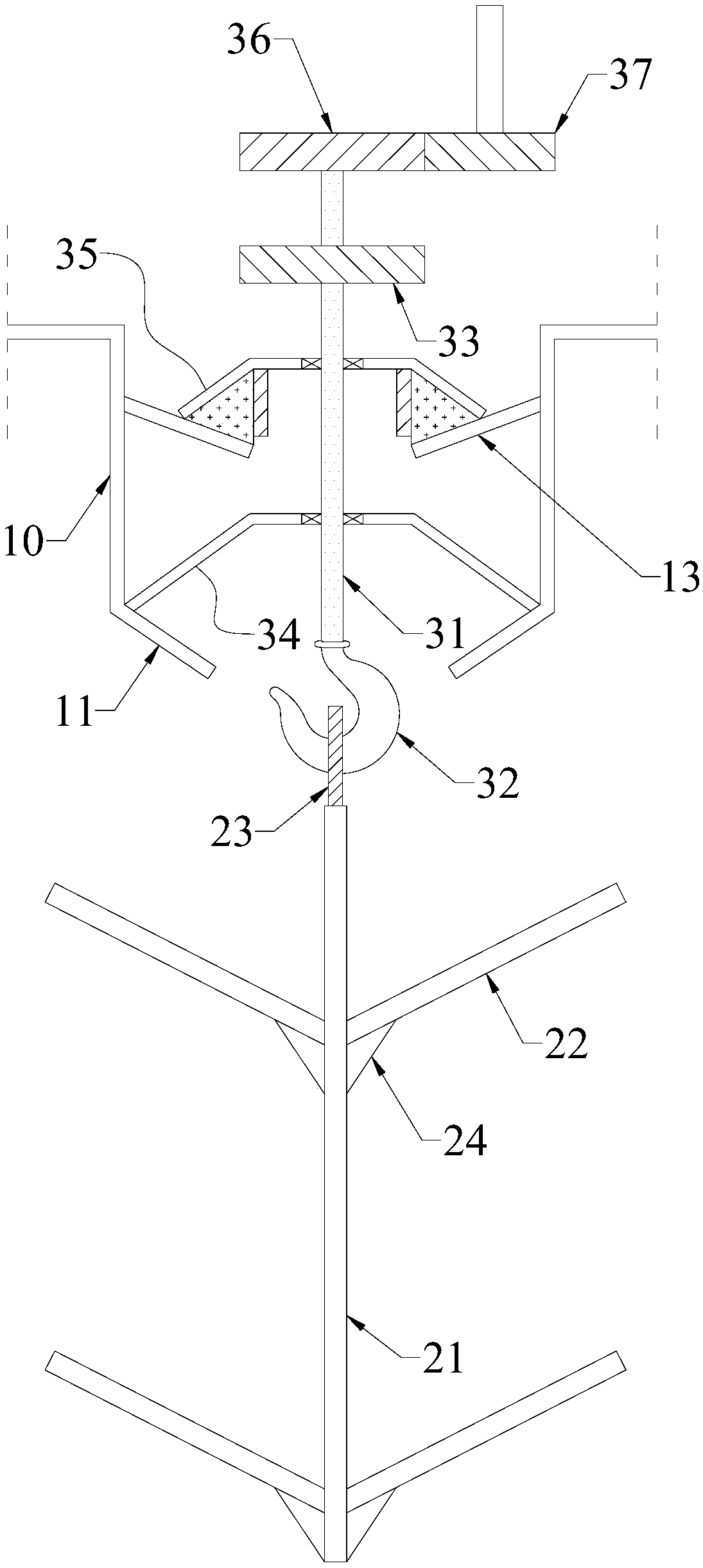
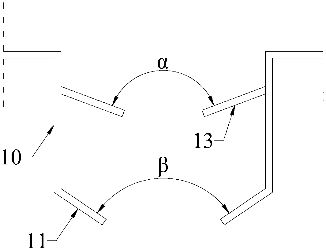
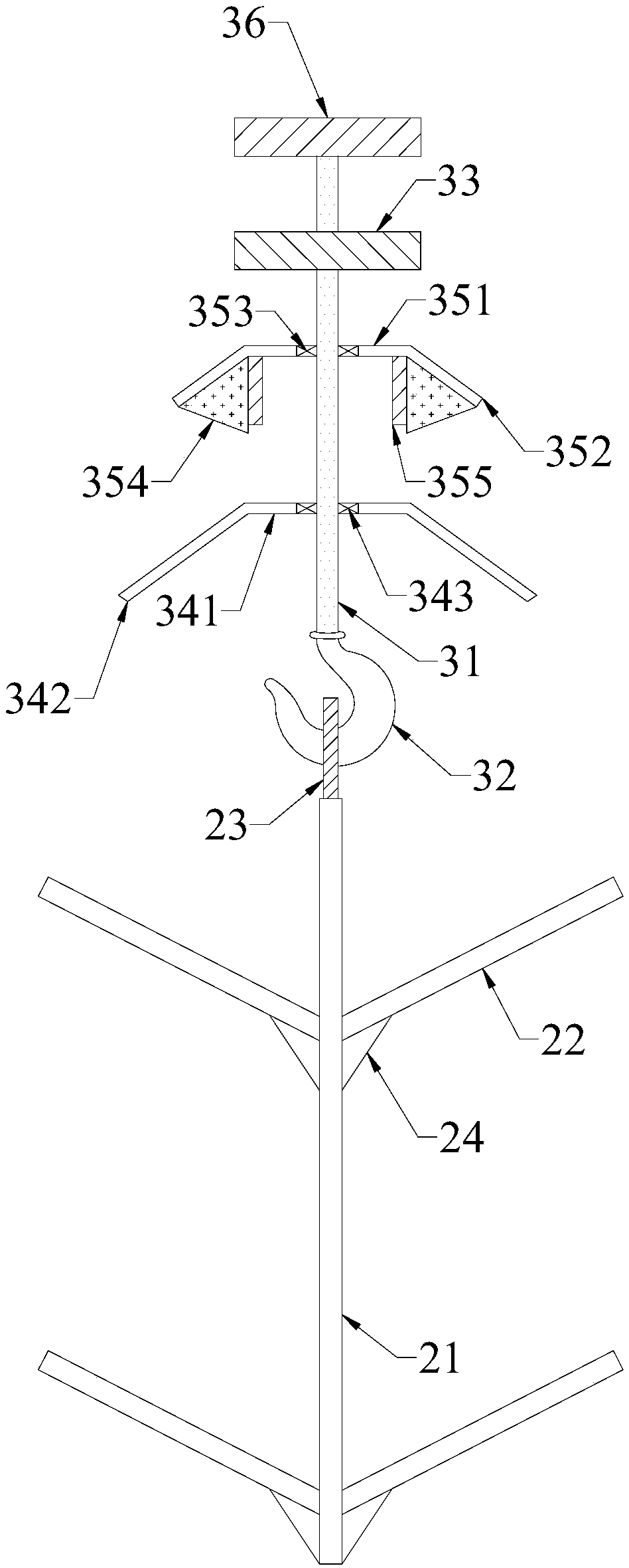
[0014] Such as Figure 1~3 As shown, the special hanger for shot blasting of the engine casting cylinder includes a shot blasting machine, the shot blasting machine is provided with a guide groove 10 with an open lower end, and the guide groove 10 communicates with the shot blasting chamber inside the shot blasting machine; The special hanger for shot blasting of engine casting cylinder includes a lower hanging rod 21, a plurality of inclined rods 22 arranged outside the lower hanging rod 21, a lifting lug 23 fixed on the upper end of the lower hanging rod 21, and a hook matching the lifting lug 23...


PUM


Abstract

The invention relates to a dedicated hanging rack for shot blasting of a cast cylinder block of an engine. The dedicated hanging rack for shot blasting of the cast cylinder block of the engine comprises a lower hanging rod, multiple inclined rods arranged on the outer side of the lower hanging rod, a lifting lug fixedly arranged at the upper end of the lower hanging rod, a lifting hook matched with the lifting lug and an upper hanging rod. The two sides of a guide groove are provided with first inclined plates which are mutually symmetrical. The outer side of the upper hanging rod is sleeved with a first baffle. The two sides of the guide groove are further provided with second inclined plates which are mutually symmetrical. The outer side of the upper hanging rod is further sleeved with asecond baffle. Elastic rods with triangular cross sections are arranged between second inclined plate portions and the second inclined plates. The side, close to the upper hanging rod, of each elastic rod is fixedly provided with a plate-shaped electromagnet. The upper end of the upper hanging rod is fixedly provided with a driven wheel. In the shot blasting process, the cast cylinder block of the engine can rotate, a shot blasting dead angle is avoided, the shot blasting effect is good, and the shot blasting efficiency is high. The seal performance between the dedicated hanging rack and a guide groove in a shot blasting machine is good, it is avoided that shot blasting dust overflows, and the shot blasting dust is not prone to accumulating in the guide groove.

Description

technical field [0001] The invention relates to a special hanger for shot blasting of engine casting cylinders, which belongs to the technical field of engine manufacturing. Background technique [0002] Cast engine blocks are usually made using the die-casting process, which is characterized by the use of mold cavities to apply high pressure to molten metal. The die-casting process is especially suitable for manufacturing a large number of small and medium-sized castings, so die-casting is the most widely used of various casting processes. Compared with other casting technologies, die casting has a flatter surface and higher dimensional consistency. [0003] After the die-casting of the engine block is completed, it must be shot blasted. However, in the current shot blasting machine, in order to ensure continuous production, the engine casting cylinder is usually hung on the hanger, and the hanger can be pulled by the traction belt or the traction chain according to the p...

Claims


Application Information

Patent Timeline
Patent Type & Authority Applications(China)
IPC IPC(8): B24C9/00
CPCB24C9/00
Inventor 张京伟黄光伟尚红标汪贞芳王跃
Owner HEFEI JAC CASTING
Why Eureka
Try Eureka