
Ear handle injection molding module

A technology of injection molding and ear handles, which is applied in the field of ear handle injection modules, can solve the problems of low injection molding efficiency of earphone wires, lower injection efficiency of earphone wires, and low quality of earphone wires, so as to improve injection molding efficiency, avoid crushing, and improve quality effect

Active Publication Date: 2021-01-29
雅刚电子(惠州)有限公司
View PDF10 Cites 0 Cited by
  • Summary
  • Abstract
  • Description
  • Claims
  • Application Information

AI Technical Summary

Problems solved by technology

[0004] However, the traditional ear handle injection mold uses two sets of molds for injection molding. After one is injected, the earphone wire must be removed and placed on another mold for injection molding, which will greatly reduce the injection molding efficiency of the earphone wire; and, When replacing the injection mold, the ear handle of the lower half of the injection molded part must be accurately embedded in the groove of the upper mold of the second set of molds, so that the ear handle of the earphone can be completely injected. If it is placed in the groove of the upper mold, the ear handle after injection molding will not completely cover the earphone wire, and the earphone wire may also be pressed by the upper mold, resulting in low quality of the earphone wire and reducing the ear handle of the earphone. Quality, which further leads to inefficient injection molding of earphone wires

Method used


Image

  • Ear handle injection molding module
  • Ear handle injection molding module
  • Ear handle injection molding module

Examples


Embodiment Construction

[0030] In order to facilitate the understanding of the present invention, the present invention will be described more fully below with reference to the associated drawings. Preferred embodiments of the invention are shown in the accompanying drawings. However, the present invention can be embodied in many different forms and is not limited to the embodiments described herein. On the contrary, the purpose of providing these embodiments is to make the disclosure of the present invention more thorough and comprehensive.

[0031] It should be noted that when an element is referred to as being “fixed” to another element, it can be directly on the other element or there can also be an intervening element. When an element is referred to as being "connected to" another element, it can be directly connected to the other element or intervening elements may also be present. The terms "vertical," "horizontal," "left," "right," and similar expressions are used herein for purposes of ill...


PUM


Abstract

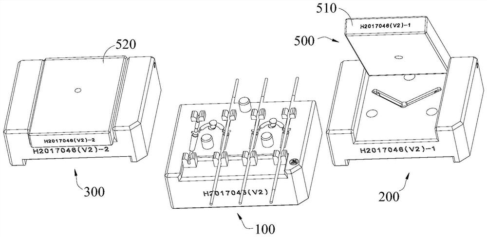
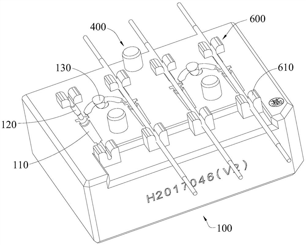
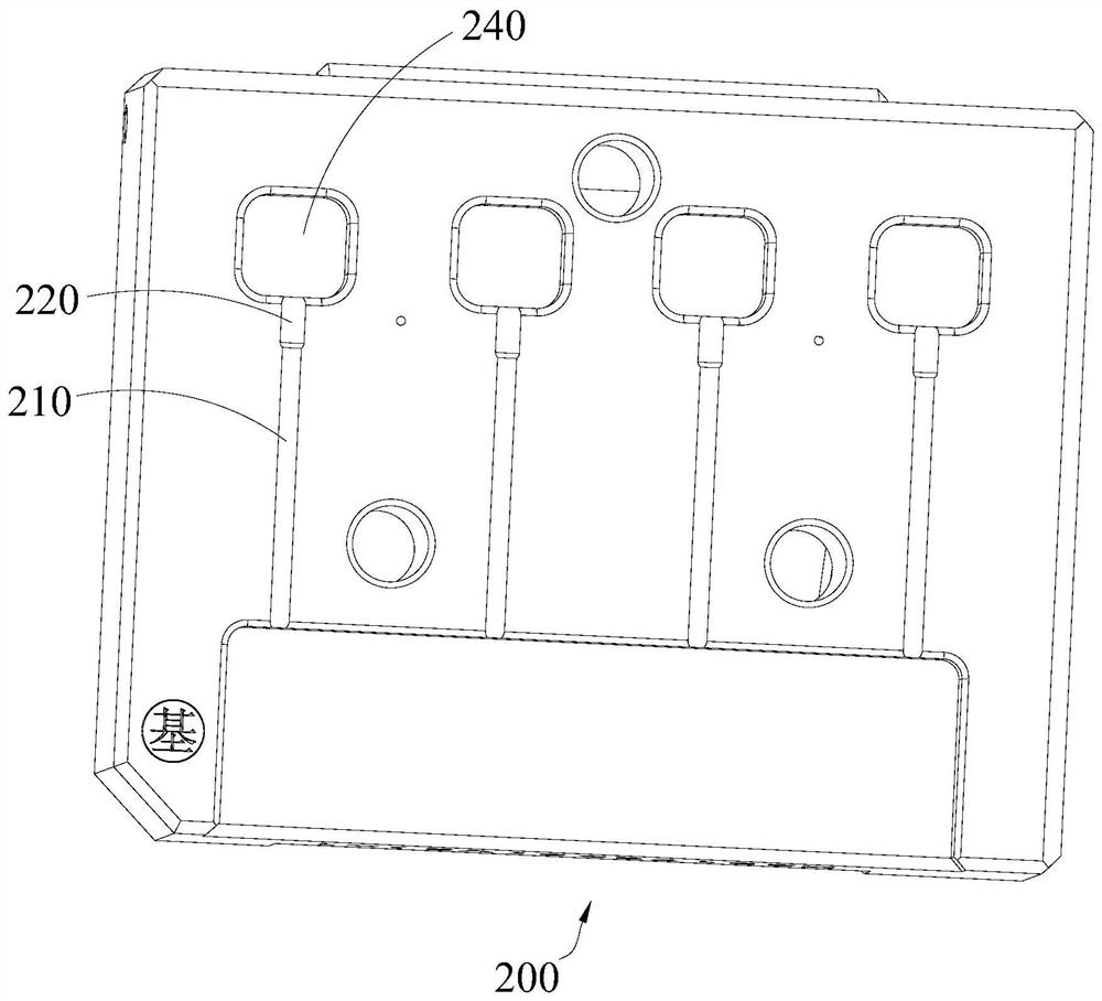
The invention discloses an ear handle injection molding module, which comprises an injection molding bottom mold, an injection molding lower mold and an injection molding upper mold. The first avoidance line groove is connected; the injection molding lower mold is provided with a line-holding half groove and a second avoidance line groove, and the line-accommodating half groove is connected with the second avoidance line groove; the injection molding upper mold is provided with a second ear handle molding cavity and The third avoidance line groove, the second lug molding cavity communicates with the third avoidance line groove; the injection lower mold is used to cover the injection bottom mold, so that the first ear handle forming cavity communicates with the line half groove; The injection molding upper mold is used to cover the injection molding bottom mold, so that the first lug molding cavity communicates with the second lug molding cavity. The invention can save an injection mold and reduce the cost of injection molding. It can also avoid the situation that there is no complete injection molding, so that the quality of the earphone wire can be improved, and the production efficiency of the ear handle injection molding can be further improved.

Description

technical field [0001] The invention relates to the field of earphone injection molding structures, in particular to an ear handle injection molding module. Background technique [0002] There are ear shells and ear handles on the earphones. The ear handles are clipped on the ear shells to protect the earphone wires. The ear shells are used as in-ear earphone components to be placed on the ears, and the ear shells A loudspeaker structure is arranged inside, so that music can be played after the ear shell is placed in the ear, realizing the function of the earphone. [0003] In the traditional injection molding method of ear handles of earphones, there are two sets of molds, and each set of molds includes an upper mold and a lower mold. When injection molding is performed, the earphone wire is placed on the lower mold of the first set of molds. , and then place the corresponding upper mold on the lower mold to inject glue, so that the lower half of the ear handle can be inje...

Claims


Application Information

Patent Timeline
Patent Type & Authority Patents(China)
IPC IPC(8): B29C45/26
CPCB29C45/26
Inventor 刘世忠
Owner 雅刚电子(惠州)有限公司
Learn More