
Lifting mechanism and photocuring 3D printing device

A lifting mechanism and printing platform technology, applied in the field of 3D printing, can solve the problems of easy loss of balls, shaking of the printing platform, and difficult replacement of parts, so as to achieve the effects of not being easily damaged and falling off, avoiding assembly deviation, and easy replacement

Active Publication Date: 2019-03-12
SHENZHEN ANYCUBIC TECH CO LTD
View PDF13 Cites 12 Cited by
  • Summary
  • Abstract
  • Description
  • Claims
  • Application Information

AI Technical Summary

Problems solved by technology

The installation of the guide rail and the support plate and the support plate and the base are slightly deviated, which will cause the slider to not slide smoothly and precisely on the guide rail, and will also cause the printing platform to shake or even get stuck during the lifting process
[0009] In addition, balls are used to slide between the slider and the guide rail of this lifting mechanism, and the balls are prone to wear and tear, and parts are not easy to replace

Method used


Image

  • Lifting mechanism and photocuring 3D printing device
  • Lifting mechanism and photocuring 3D printing device
  • Lifting mechanism and photocuring 3D printing device

Examples


Embodiment Construction

[0046] The following will clearly and completely describe the technical solutions in the embodiments of the present invention with reference to the drawings in the embodiments of the present invention. The described embodiments are only some of the embodiments of the present invention, but not all of them, nor are they intended to limit the technical solution of the present invention.

[0047] Unless otherwise defined, the technical terms or scientific terms used herein shall have the usual meanings understood by those skilled in the art to which the present invention belongs. "First", "second" and similar words used in the present invention do not indicate any order, quantity or importance, but are only used to distinguish different components. "Comprising" or "comprising" and similar words mean that the elements or items appearing before the word include the elements or items listed after the word and their equivalents, without excluding other elements or items. "Up", "Down...


PUM


Abstract

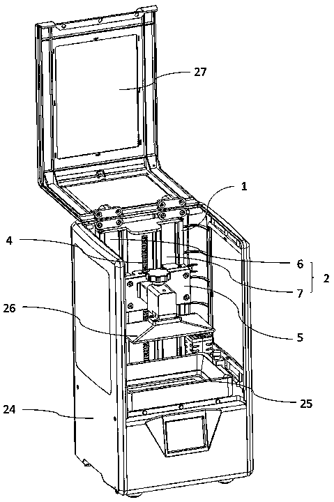
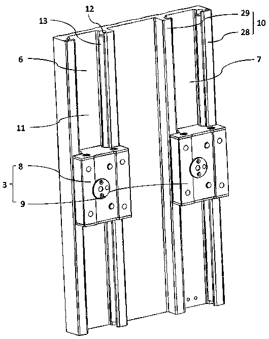
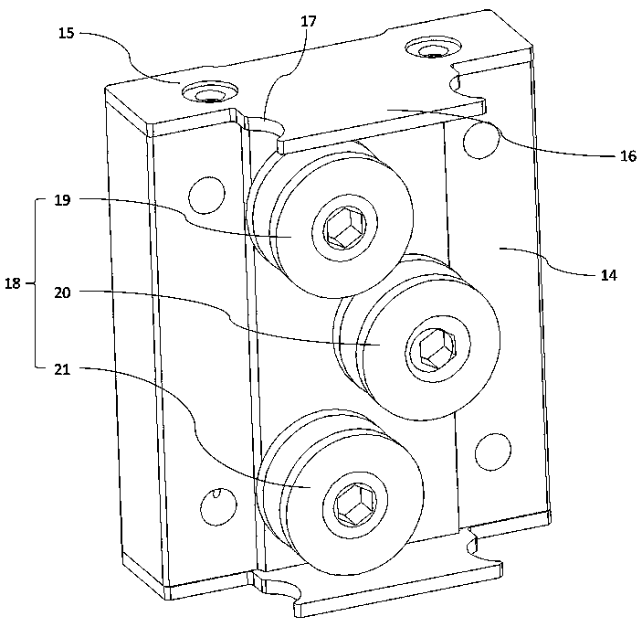
A lifting mechanism comprises a first plate, a guide rail, sliding blocks, a driving part and a connecting part. The guide rail comprises at least two sliding grooves, wherein the sliding grooves areformed in a first surface of the first plate, are parallel to one another and extend in a first direction, the first direction is parallel to the first surface of the first plate, and the sliding grooves and the first plate are integrally formed. At least one sliding block is arranged in each sliding groove and is in sliding fit with the corresponding sliding groove. The connecting part is connected with the sliding blocks, the driving part and a printing platform so that the connecting part can be driven by the driving part to drive the sliding blocks and the printing platform to move in thefirst direction. Due to the fact that the sliding groove-type guide rail, the sliding grooves and a supporting plate are integrally arranged and the positions of sliding components of the sliding blocks can be adjusted so that the accuracy of sliding fit between the sliding blocks and the sliding grooves can be sufficiently ensured, sufficient compensation for sliding resistance, caused by skewingof a transmission component, between the sliding blocks and the sliding grooves is also ensured, and the sliding smoothness of the sliding blocks can also be ensured even if the transmission component skews to a large extent.

Description

technical field [0001] The present invention relates to the technical field of 3D printing, in particular to a light-curing 3D printing device, and more particularly to a lifting mechanism of a light-curing 3D printing device. Background technique [0002] Light-curing 3D printing technology mainly uses photosensitive resin as the material, and the photosensitive resin is cured layer by layer by ultraviolet light or other light sources, and finally a complete product is obtained. It has the advantages of high molding precision and good surface effect after molding, and can meet the applications in many fields such as aerospace, construction, medical treatment, and mold manufacturing. [0003] The specific process of light-curing 3D printing is as follows: the thickness of the preformed first layer of resin layer is retained between the surface of the forming platform and the release film at the bottom of the resin tank, and the resin in the resin tank enters the reserved spa...

Claims


Application Information

Patent Timeline
IPC IPC(8): B29C64/124B29C64/232B29C64/245B33Y30/00
CPCB29C64/124B29C64/232B29C64/245B33Y30/00
Inventor 欧阳欣周承立张卫嘉欧阳露
Owner SHENZHEN ANYCUBIC TECH CO LTD
Learn More