Charging method based on constant current-constant voltage output characteristics of wireless power transfer system

A technology of wireless power transmission and constant voltage output, which is applied to battery circuit devices, current collectors, electric vehicles, etc., can solve the problems of rapid battery capacity drop and shortened cycle life, and achieve stable output and strong robustness Effect

Active Publication Date: 2021-07-20
XIAN UNIV OF TECH
View PDF7 Cites 0 Cited by
  • Summary
  • Abstract
  • Description
  • Claims
  • Application Information

AI Technical Summary

Problems solved by technology

The long service life of the battery depends to a large extent on the correct charging method. Numerous facts have proved that even the best battery is prone to serious problems such as rapid decline in battery capacity and shortened cycle life under inappropriate charging methods.
With the development and application of charging technology, high safety, high reliability and high efficiency requirements are put forward for battery charging technology, which makes battery charging technology face higher challenges

Method used


Image

  • Charging method based on constant current-constant voltage output characteristics of wireless power transfer system
  • Charging method based on constant current-constant voltage output characteristics of wireless power transfer system
  • Charging method based on constant current-constant voltage output characteristics of wireless power transfer system

Examples


Embodiment

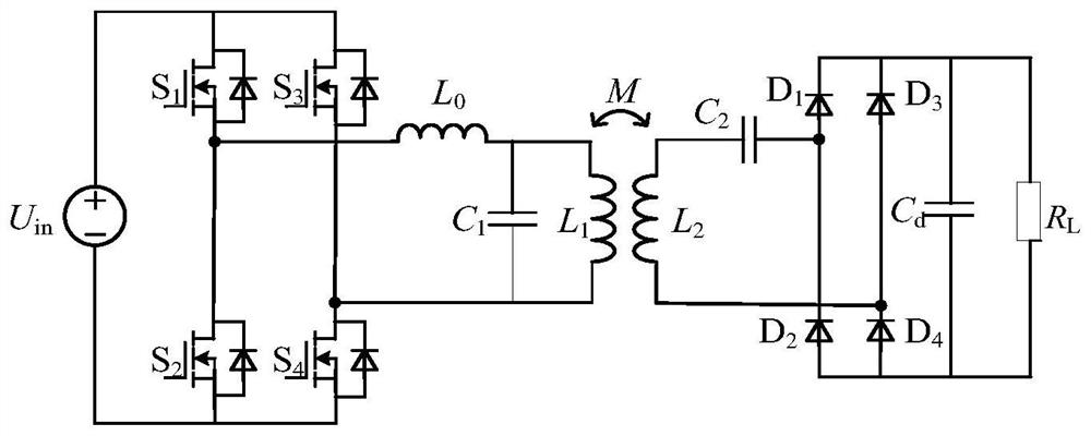
[0148] The research method of the present invention is carried out simulation analysis, in the parameter calculation process, known simulation parameters have: DC voltage source output voltage is 100V, high-frequency inverter output square wave AC voltage effective value U 1v =90V, resonant frequency f 0 = 85kHz;

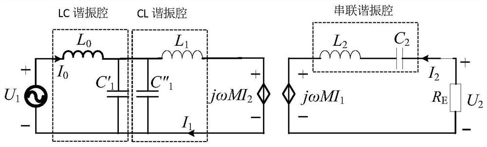
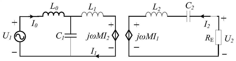
[0149] Set the self-inductance L of the primary side coil of the coupler 1 =125μH, the self-inductance L of the secondary side coil 2 =125μH, mutual inductance M=37.5μH (that is, coupling coefficient k=0.3), L 0 = 125 μH. Parallel capacitance C on the primary side 1 =56.09nF, the secondary side series capacitor C 2 =28.05nF, from the formula (18), when the coupling coefficient k=0.3, ω nB =1.144, that is, the high operating frequency point f 0B =1.144, f 0 = 97kHz; do not consider the application of complex working conditions in the charging process of the battery, so only the influence of its internal resistance is considered. In the simulation, the resista...


PUM


Abstract

The invention discloses a charging method based on the constant current-constant voltage output characteristics of a wireless energy transmission system, adopts an LC / S compensation topology, and replaces the DC input voltage in the LC / S compensation topology with a sinusoidal voltage source with a frequency equal to the switching frequency of an inverter Source and inverter, ignoring the parasitic resistance of the inductor and capacitor, the loosely coupled transformer is replaced by the mutual inductance model, and the equivalent mutual inductance model circuit is obtained; the full-bridge rectifier circuit is replaced by the equivalent load resistance R E Instead, the primary side parallel compensation capacitor C 1 split into capacitor C 1 ' and C 1 "Constitute LC, CL and series resonant cavity, obtain simplified circuit; define transconductance gain G i and voltage gain G v , to obtain the frequency point when the radio transmission system has constant current output characteristics and constant voltage output characteristics; the system is at the obtained frequency point to perform constant current-constant voltage segmental charging. The method of the invention realizes the constant-current or constant-voltage output characteristics of wireless energy transmission through the same compensation topology conversion operating frequency point, thereby realizing segmental charging of the battery.

Description

technical field [0001] The invention belongs to the technical field of wireless power transmission, and in particular relates to a charging method based on the constant current-constant voltage output characteristics of a wireless power transmission system. Background technique [0002] Wireless power transmission technology solves the defect of traditional wire direct contact power supply, and is a safe, reliable and convenient power transmission method. The emergence of wireless power transmission technology makes it possible for electrical equipment to get rid of the shackles of cables. The popularization of this "energy Wifi" technology in the future will bring great convenience to people's lives. The development and further breakthrough of this technology will have a profound impact on electric vehicles, medical care, industry, electronics and other fields. [0003] Wireless power transmission is mainly aimed at charging mobile power-consuming equipment, and mobile pow...

Claims


Application Information

Patent Timeline
Patent Type & Authority Patents(China)
IPC IPC(8): H02J50/12H02J7/02
CPCH02J7/025H02J50/12
Inventor 尹有为王泉
Owner XIAN UNIV OF TECH
Why Eureka
Try Eureka