Wireless charging circuit, control method thereof and electronic equipment

A technology of wireless charging and control method, which is applied in the direction of battery circuit devices, charging stations, circuit devices, etc., which can solve the problems of reduced transmission efficiency, increased reactive power of circuit transmission, and safety issues, so as to improve output power and transmission efficiency Effect

Pending Publication Date: 2022-03-25
金琥新能源汽车(成都)有限公司
View PDF0 Cites 0 Cited by
  • Summary
  • Abstract
  • Description
  • Claims
  • Application Information

AI Technical Summary

Problems solved by technology

At present, the charging technology is basically charging the charging pile, which is inconvenient. It has both mechanical loss and safety problems, which affects the popularization and promotion of electric vehicles. However, wireless charging of electric vehicles will not be limited by the power capacity, reducing the impact on the battery. Rely on, improve the cruising range, so research and development of electric vehicle wireless charging technology is imperative
[0003] At present, the loosely coupled transformer in the wireless charging circuit has the disadvantages of large leakage inductance and small excitation inductance, which leads to the increase of reactive power transmitted by the circuit and the decrease of transmission efficiency.

Method used


Image

  • Wireless charging circuit, control method thereof and electronic equipment
  • Wireless charging circuit, control method thereof and electronic equipment
  • Wireless charging circuit, control method thereof and electronic equipment

Examples


Embodiment Construction

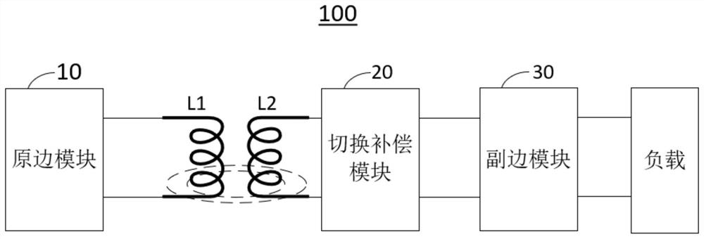
[0047] As described in the background technology, at present, the loosely coupled transformer in the wireless charging circuit has the disadvantages of large leakage inductance and small excitation inductance, which leads to an increase in reactive power transmitted by the circuit and a decrease in transmission efficiency.

[0048] The problems existing in the prior art are all the results obtained by the inventor after practice and careful research. Therefore, the discovery process of the above problems and the solutions to the above problems proposed by the embodiments of the present invention below should all be It is the contribution made by the inventor during the invention process.

[0049]In order to make the purpose, technical solutions and advantages of the embodiments of the present invention clearer, the technical solutions in the embodiments of the present invention will be clearly and completely described below in conjunction with the drawings in the embodiments of...


PUM


Abstract

The invention provides a wireless charging circuit, a control method thereof and electronic equipment, and relates to the field of wireless charging. In the wireless charging circuit, a primary side module is connected with a primary side inductor, the primary side inductor is coupled with a secondary side inductor, the secondary side inductor, a switching compensation module and a secondary side module are sequentially connected, the primary side module is externally connected with an input voltage, and the secondary side module and the switching compensation module are both connected with a load; the switching compensation module is used for switching a compensation mode according to the voltage of the load; when the voltage of the load is lower than a set threshold value, the switching compensation module is switched to a first compensation mode to realize constant current output; when the voltage of the load is larger than or equal to the threshold value, the switching compensation module is switched to a second compensation mode, and constant voltage output is achieved. In the application, the switching compensation module can be switched to different compensation modes according to the voltage condition of the load, and constant-current and constant-voltage wireless charging can be realized, so that the output power and transmission efficiency of electric energy transmission are improved.

Description

technical field [0001] The present invention relates to the field of wireless charging, in particular to a wireless charging circuit, a control method thereof, and electronic equipment. Background technique [0002] At present, there is a shortage of renewable resources in the world and serious environmental pollution. The development of new energy vehicles with no pollution and zero emissions has become a strategic policy for sustainable development of all countries. At present, the charging technology is basically charging the charging pile, which is inconvenient. It has both mechanical loss and safety problems, which affects the popularization and promotion of electric vehicles. However, wireless charging of electric vehicles will not be limited by the power capacity, reducing the impact on the battery. Therefore, research and development of electric vehicle wireless charging technology is imperative. [0003] At present, the loosely coupled transformer in the wireless c...

Claims


Application Information

Patent Timeline
IPC IPC(8): H02J50/10H02J7/00H02J7/04B60L53/12
CPCH02J50/10H02J7/00712H02J7/04B60L53/12Y02T10/70Y02T10/7072Y02T90/14
Inventor 刘云
Owner 金琥新能源汽车(成都)有限公司
Why Eureka
Try Eureka