Inspection equipment

A technology for inspecting equipment and components, which is applied in the field of radiographic inspection equipment and inspection equipment, can solve the problems of oversize, inconvenient use, disassembly, etc., and achieve the effect of convenient use

Pending Publication Date: 2019-03-19
TSINGHUA UNIV +2
View PDF0 Cites 5 Cited by
  • Summary
  • Abstract
  • Description
  • Claims
  • Application Information

AI Technical Summary

Problems solved by technology

[0003] The inventor found that: the existing self-propelled large object inspection equipment needs to be disassembled dur

Method used


Image

  • Inspection equipment
  • Inspection equipment
  • Inspection equipment

Examples


Example Embodiment

[0040] Combine below Figure 1 ~ Figure 4 The technical solution provided by the present invention is described in more detail.
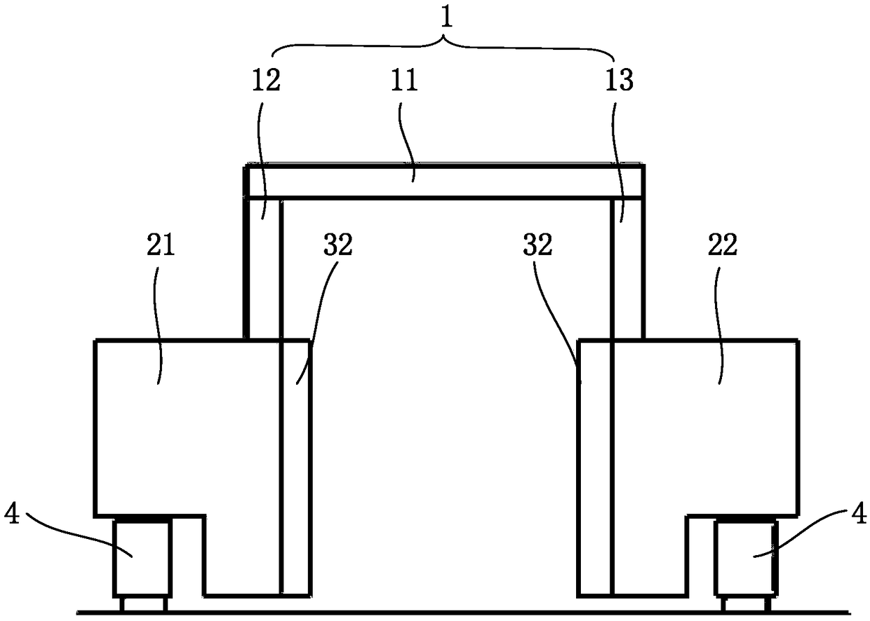
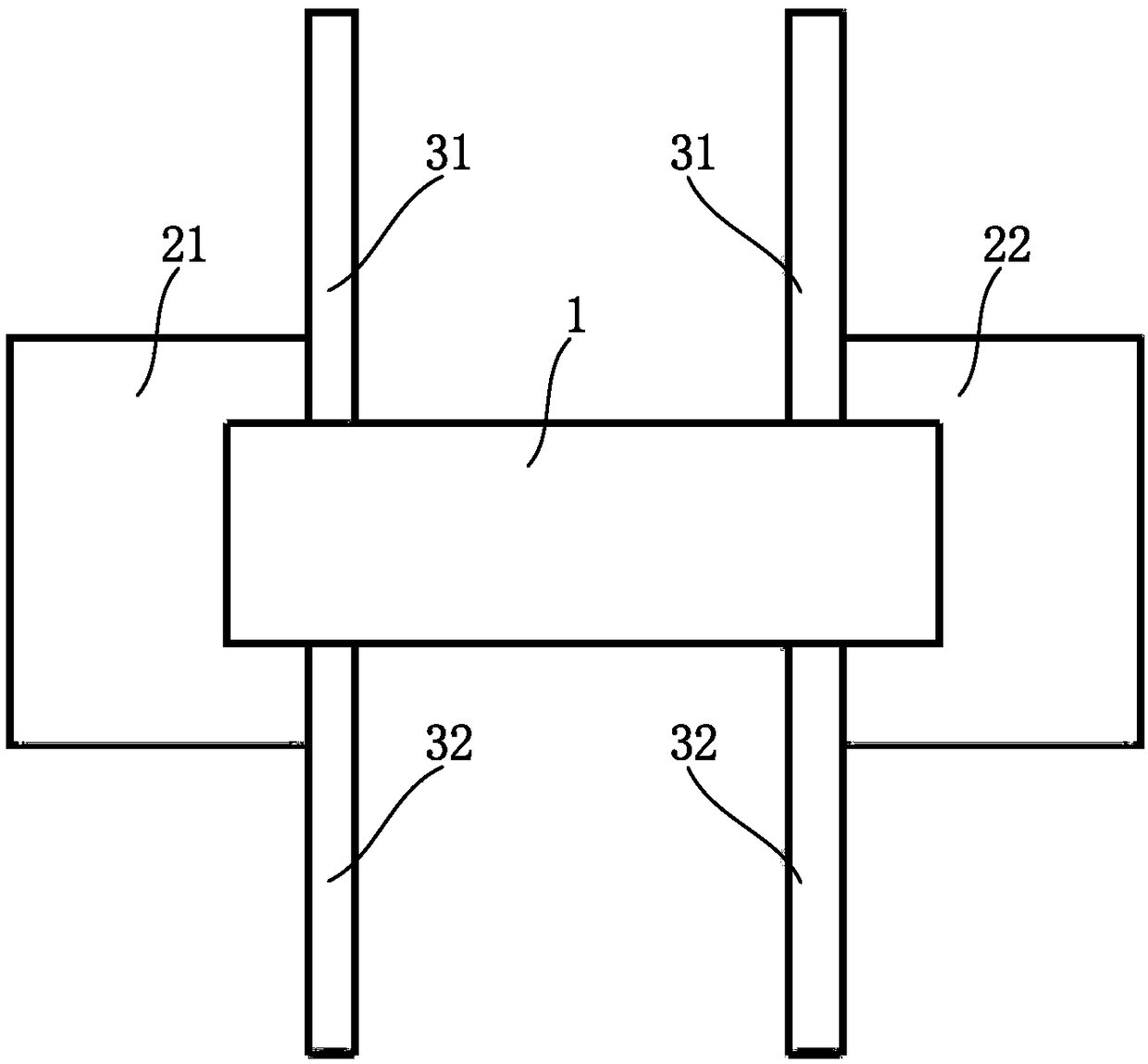
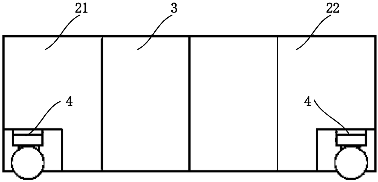
[0041] See figure 1 , The embodiment of the present invention provides an inspection equipment, which includes a boom 1, a cabin assembly 2 and a walking device 4. The boom 1 is arranged on the cabin assembly 2 in a liftable manner; the walking device 4 is arranged at the bottom of the cabin assembly 2 and at least partially located directly under the cabin assembly 2.

[0042] The inspection equipment is formed with inspection channels for scanning vehicles or containers. The radiation detection device includes a radiation source and a detector. The cabin assembly 2 is used to install components such as a radiation source. The boom 1 is used to install detectors and other components. The boom 1 is a liftable structure. During transportation, the boom 1 is retracted; when working, the boom 1 is opened to avoid checking the super high equipment during ...


PUM


Abstract

The invention discloses inspection equipment, and relates to the field of radiographic inspection equipment. The inspection equipment is used for optimizing a structure of the inspection equipment. The inspection equipment comprises an arm rest, a cabin assembly and a walking device. The arm rest can be arranged on the cabin assembly in a lifting manner, the walking device is arranged at the bottom of the cabin assembly, and at least one part of the cabin assembly is located under the cabin assembly. According to the technical scheme, the arm rest adopts a stretchable structure so that the height of the inspection equipment is variable. In the using state, the arm rest is located in an extending state so that to-be-detected cargoes can pass an inspection channel formed by the arm rest; ifa scanning device needs to be transported, the arm rest is retracted to reduce the height of the scanning device, and the transportation requirement is thus met.

Description

technical field [0001] The invention relates to the field of radiation inspection equipment, in particular to an inspection equipment. Background technique [0002] The self-propelled large object inspection equipment includes a gantry, a fixed beam and a traveling device. The fixed beam is installed on the gantry frame, and the traveling device is installed on the bottom of the fixed beam. Each part is separated, and after being transported to the work site, each part is installed together and debugged. [0003] The inventor found that: the existing self-propelled large object inspection equipment needs to be disassembled during transportation due to its large size; it needs to be reinstalled and re-adjusted on site, which is inconvenient to use. Contents of the invention [0004] The invention proposes an inspection device for optimizing the structure of the inspection device. [0005] The invention provides an inspection device, comprising: [0006] jib; [0007] a...

Claims


Application Information

Patent Timeline
IPC IPC(8): G01V5/00
CPCG01V5/0016
Inventor 宋全伟樊旭平孟辉高克金胡煜孙尚民周合军
Owner TSINGHUA UNIV
Why Eureka
Try Eureka