
Display device, producing method and wearable equipment

A display device and display panel technology, applied in optical elements, optics, instruments, etc., can solve problems such as focal length and vergence that are prone to discomfort, unable to achieve large depth of field and stereoscopic, and unable to present stereoscopic vision with one eye.

Pending Publication Date: 2019-03-19
BOE TECH GRP CO LTD
View PDF5 Cites 8 Cited by
  • Summary
  • Abstract
  • Description
  • Claims
  • Application Information

AI Technical Summary

Problems solved by technology

This method cannot present stereoscopic vision with one eye, and is limited by the brain's ability to fuse images. It cannot achieve a large depth of field and stereoscopic effect. There are problems with focal length and convergence, which can easily cause discomfort.
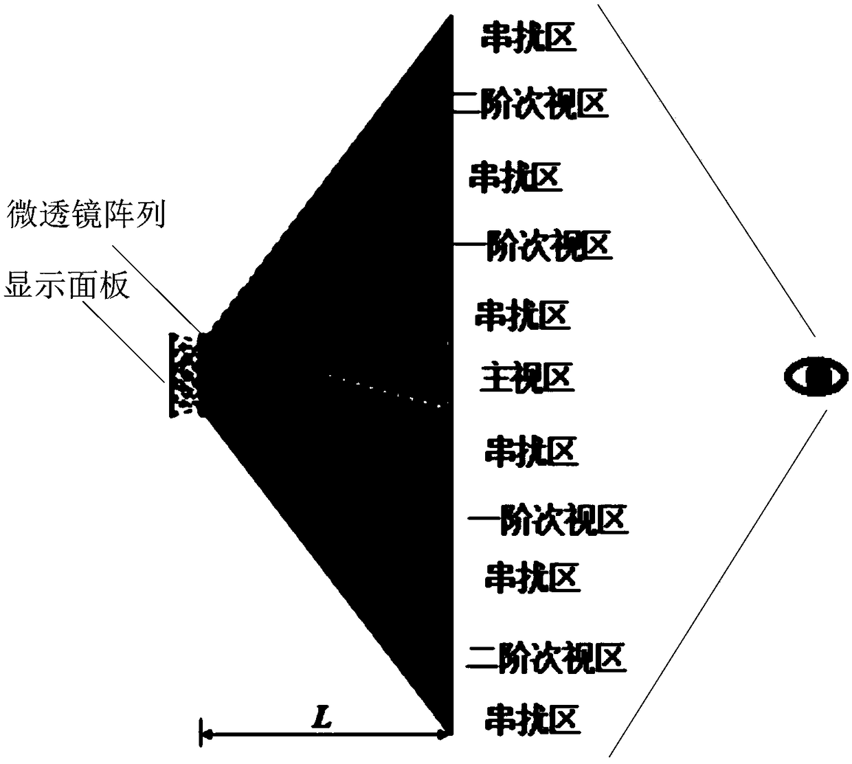
[0003] Relying on the principle of integrated light field to realize VR head-mounted light field display can produce monocular focus adjustment, and solve the problem of convergence while realizing monocular stereo vision, so as to solve the disadvantages of traditional three-dimensional display, but the existing integrated light field display generally has a viewing angle narrow question

Method used


Image

  • Display device, producing method and wearable equipment
  • Display device, producing method and wearable equipment
  • Display device, producing method and wearable equipment

Examples


Embodiment Construction

[0035] In order to illustrate the present invention more clearly, the present invention will be further described below in conjunction with preferred embodiments and accompanying drawings. Similar parts in the figures are denoted by the same reference numerals. Those skilled in the art should understand that the content specifically described below is illustrative rather than restrictive, and should not limit the protection scope of the present invention.

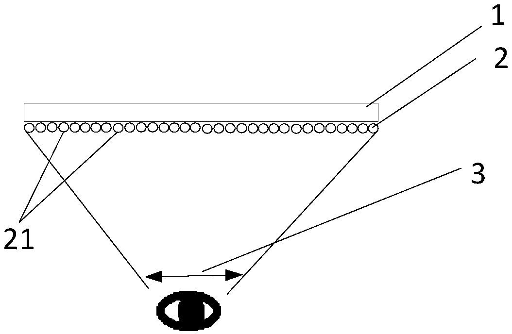
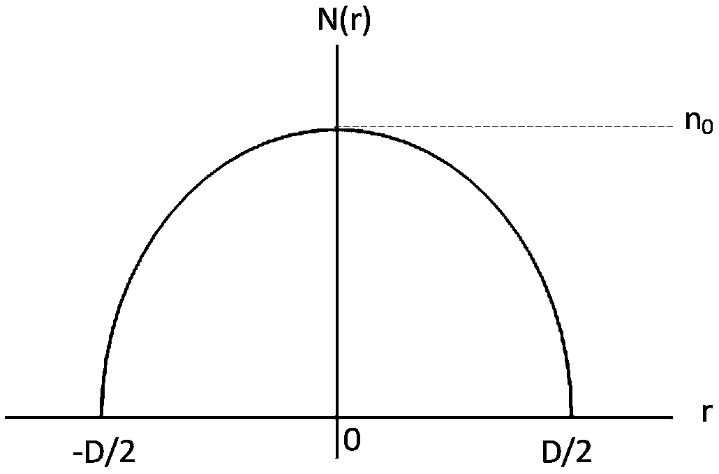
[0036] Such as figure 2 As shown, one embodiment of the present invention provides a display device, including a display panel; a microlens array located on the light-emitting side of the display panel, wherein the microlens array includes a plurality of microlens elements arranged in an array, wherein The refractive index of each microlens element decreases radially with the optical axis of the microlens element as the center.

[0037] In a specific example, the display device includes a display panel 1 and a microlens ...


PUM


Abstract

The invention discloses a display device, a producing method and wearable equipment. The display device comprises a display panel and a micro lens array which is located on the light outlet side of the display panel, wherein the micro lens array comprises multiple lens elements which are arranged in array, and the reflection rate of each micro lens element gradually diminishes in the radial direction taking the optical axis of the micro lens element as the center. The display device has the advantages that the micro lens array with gradually changed reflection rate is adopted by the display device, the displaying of a near-eye optical field is achieved while the constraint on the optical path of image display light is achieved by controlling the angle of outlet light, so the outlet light is defined in a corresponding region, the crosstalk caused by the overlapping of the outlet lights of the adjacent lens elements is avoided, and the viewing region is increased while the viewing effectis improved.

Description

technical field [0001] The present invention relates to the field of display technology, in particular to a display device, a manufacturing method and a wearable device. Background technique [0002] The realization of three-dimensional information display in near-eye display devices mostly adopts the principle of binocular parallax. For example, VR near-eye display technology displays the images of the left and right eyes on the near-eye displays corresponding to the left and right eyes, and the eyes obtain the information with differences in the mind. Can produce stereoscopic vision. This method cannot present stereoscopic vision with one eye, and is limited by the brain's ability to fuse images. It cannot achieve a large depth of field and three-dimensionality. There are problems with focal length and convergence, which can easily cause discomfort. [0003] Relying on the principle of integrated light field to realize VR head-mounted light field display can produce monoc...

Claims


Application Information

Patent Timeline
Patent Type & Authority Applications(China)
IPC IPC(8): G02B27/01G02B27/22
CPCG02B27/0101G02B30/27
Inventor 周春苗
Owner BOE TECH GRP CO LTD
Learn More