
Method for diagnosing input signal fault of PLC system using counter

A technology of input signal and signal failure, applied in general control systems, control/regulation systems, testing/monitoring control systems, etc., can solve problems such as reducing production efficiency, failing to alert operators to equipment failures, and taking long time to deal with failures. The effect of improving response speed and saving troubleshooting time

Active Publication Date: 2019-03-19
河钢数字信达(邯郸)科技有限公司
View PDF6 Cites 1 Cited by
  • Summary
  • Abstract
  • Description
  • Claims
  • Application Information

AI Technical Summary

Problems solved by technology

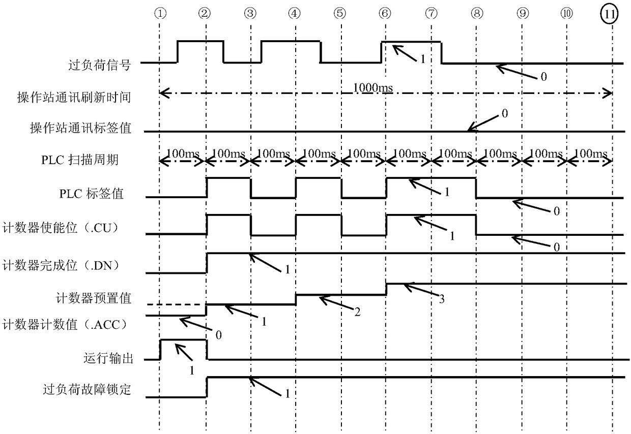
In practical applications, the external input signal of the PLC system often has a "jitter" fault phenomenon, that is, the frequency of the normal signal and the fault is less than 1 second, so because a scan cycle of the PLC system is generally tens of milliseconds, it can capture the signal fault and make it The control equipment stops running. However, since the data communication rate between the HMI monitoring system and the PLC is greater than or equal to 1 second, the signal failure cannot be captured, and the operator cannot be prompted about the cause of the equipment failure. The method of replacing the input signal of the input signal or fastening the terminal block for investigation and processing takes a long time to deal with the fault, which greatly reduces the production efficiency

Method used


Image

  • Method for diagnosing input signal fault of PLC system using counter
  • Method for diagnosing input signal fault of PLC system using counter

Examples


Embodiment Construction

[0016] The present invention will be further described below by means of embodiments in conjunction with the accompanying drawings.

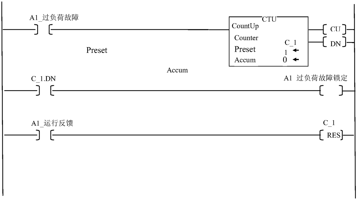
[0017] In an embodiment, a method for using a counter to diagnose a PLC system input signal fault, the steps are as follows:

[0018] Step 1: Counter instruction description. The counting instruction CTU is an output instruction, and the counter structure is shown in Table 1:

[0019] Table 1. Counter structure

[0020] mnemonic

type of data

illustrate

.CU

BOOL

Up counting enable bit --- indicates that the CTU instruction is enabled.

.DN

BOOL

Completion bit---Identifies accumulated value (.ACC)>=(preset value.PRE).

.OV

BOOL

Overflow bit --- indicates that the counter exceeds the upper limit value.

.PRE

DINT

preset value --- Specifies the value the accumulated value reaches before the instruction sets the done bit (.DN).

.ACC

DINT

Accumulated value --- I...


PUM


Abstract

The invention relates to a method for diagnosing an input signal fault of a PLC system by using a counter, and belongs to the technical field of automatic control. The method comprises the steps of assigning the fault diagnosis CTU counter to each input signal causing a controlled device to stop running; using a fault state of the input signal as an enable bit of the CTU counter, setting a presetvalue of the counter as 1, wherein a completion bit (.DN) of the counter is communicated with corresponding signal fault lock; determining the fault cause of the controlled device to stop running by checking the completion bit (.DN) of the fault diagnosis CTU counter and the corresponding signal fault lock. The method has the advantages that a PLC system input signal fault is diagnosed by using acounter programming program in the PLC controller, and the input signal fault can be quickly and accurately locked, thereby saving the fault processing time and improving the response speed of the fault processing.

Description

technical field [0001] The invention relates to a method for diagnosing input signal faults of a PLC system by using a counter, and belongs to the technical field of automatic control. technical background [0002] PLC controller is an electronic device specially designed for digital operation in industrial environment. It uses a memory that can be programmed to store instructions for performing operations such as logic operations, sequential operations, timing, counting, and arithmetic operations, and can control various types of devices through digital or analog inputs and outputs. machinery or production process. PLC controllers have been widely used in various industries such as steel, petroleum, chemical industry, electric power, building materials, machinery manufacturing, automobiles, textiles, transportation, environmental protection, cultural entertainment, etc. It has high reliability, strong anti-interference ability, powerful functions, Flexible, easy to learn ...

Claims


Application Information

Patent Timeline
IPC IPC(8): G05B23/02
CPCG05B23/0221
Inventor 王红彦王伟兵李玉杰苗贵仓李彦峰
Owner 河钢数字信达(邯郸)科技有限公司
Learn More