
Button switch with socket and control method

A control method and button technology, applied in the direction of electric switches, contact parts, electrical components, etc., can solve the problems of troublesome use process, low product reliability, and control of high-load circuits, etc., to achieve expanded use range, convenient structure assembly, The effect of increasing the load capacity

Pending Publication Date: 2019-03-19
王攀
View PDF0 Cites 0 Cited by
  • Summary
  • Abstract
  • Description
  • Claims
  • Application Information

AI Technical Summary

Problems solved by technology

[0002] The contact combination of traditional products is relatively single. There are only one normally open and one normally closed contact or only two normally open contacts, which cannot realize the structure of free combination, and users will have limitations in the use process
The movable contacts of traditional products use tension springs to hook the shrapnel of the moving contact body, which has the following advantages: 1. Difficult assembly, limited output per capita, and high cost; 2. The life of the tension spring determines the life of the product, and the life of the tension spring is generally relatively short , leading to a very short service life of traditional products; 3. In the process of controlling high-load lines, the contacts of traditional products will be bonded due to insufficient tension of the tension springs, and products with tension spring structures cannot guarantee the life of the product. Defects such as circuits that control high loads under
The self-locking hook of traditional products uses a single-sided hook, and the push rod is also one-sided, which cannot be balanced. Once the product is misplaced during assembly, the self-locking function will fail
The indicator lights of traditional products need to weld the drop-down resistor to the LED light-emitting diode first, then install it inside the product, then distort the position of the drop-down resistor, and then weld the drop-down resistor to the pin workpiece inside the product, the entire installation The welding process is very complicated, and the welding is carried out inside the product, resulting in low product reliability and easy false welding, resulting in a high failure rate of the product
There is no adapter socket for traditional products. Users need to weld the wire harness on the product by themselves during use. The use process is cumbersome, and the welded products are not easy to replace and maintain.

Method used


Image

  • Button switch with socket and control method
  • Button switch with socket and control method
  • Button switch with socket and control method

Examples


Embodiment approach 1

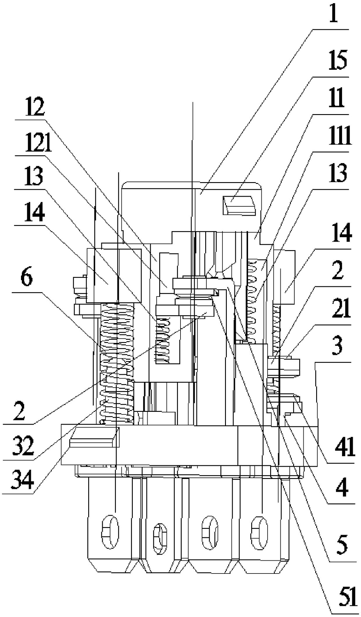
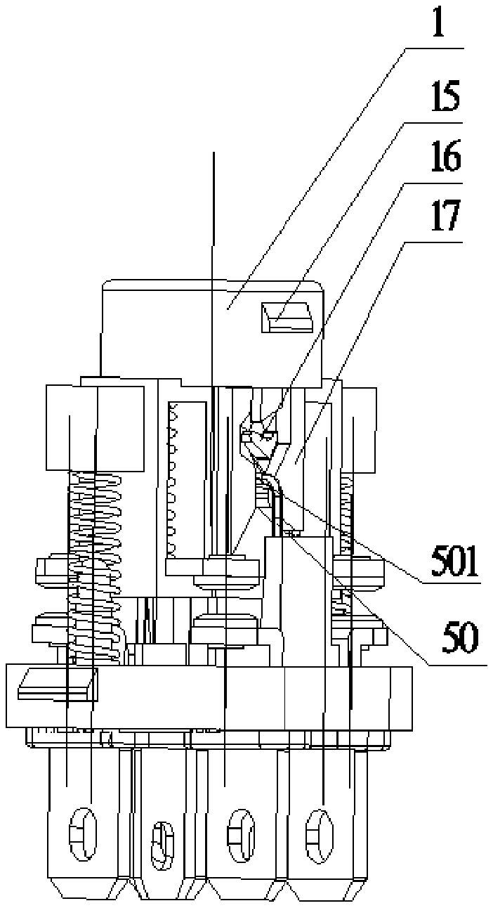
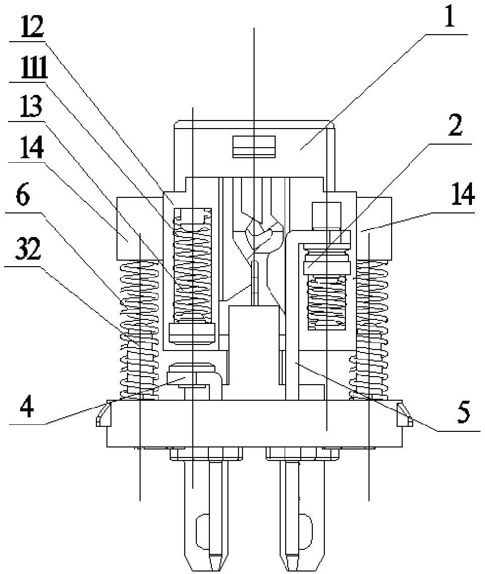
[0058] Such as figure 1 , Figure 5As shown, the push button switch with socket of the present invention includes: a push rod 1, a first push rod connection part 11 and a second push rod connection part 12 are protruded from one end thereof, and the first push rod connection part 11 and the second push rod connection part 11 The interior of the rod connecting portion 12 is respectively formed with a through first mounting portion 111 and a second mounting portion 121, and the first mounting portion 111 and the second mounting portion 121 are respectively embedded with a movable contact spring 13; the first push rod connecting portion 11 and the outer wall of the second push rod connecting portion 12 are respectively fixed with at least one stop block 14; two moving contacts 2, and the two moving contacts 2 are movably clamped on the first mounting portion 111 and the second mounting portion 111 respectively. In the part 121, the spring 13 of the movable contact is pressed aga...

Embodiment approach 2

[0072] The present invention also provides a method for controlling a button switch with a socket, wherein the method for controlling the button switch with a socket adopts the above-mentioned button switch with a socket, and the button switch with a socket in this embodiment is the same as that of Embodiment 1. The structures, working principles and beneficial effects are the same, and will not be repeated here. The control method of the button switch with socket comprises the following steps:

[0073] Step S1, press the push rod 1 downward, the movable contact 2 moves downward accordingly, and the stop spring 6 is in a compressed state under the force of pressing the push rod 1;

[0074] Step S2 , removing the active force applied to the push rod 1 , the push rod 1 moves upwards under the resilience of the stop spring 6 , and the movable contact 2 moves upward accordingly.

[0075]In a feasible embodiment, the button switch with the socket is set to a "one normally open and...


PUM


Abstract

The invention provides a button switch with a socket and a control method. The button switch comprises a push rod. One end of the push rod protrudes to form a first push rod connecting part and a second push rod connecting part, and movable contact member springs are embedded respectively. Each movable contact member spring abuts against a movable contact member, and first contacts are arranged ontwo ends of the movable contact member. A base connecting part is formed on a base. The first push rod connecting part and the second push rod connecting part can be installed on the base connectingpart. At least one stop post corresponding to a stop block is formed on the base. A number of insertion holes corresponding to the first contacts are formed in the base. Second contacts are arranged on one end of two first static contact members. Second contacts are corresponding to the first contacts on two ends of the movable contact member in a first mounting part. Third contacts are arranged on one end of two second static contact members, and are corresponding to the first contacts on two ends of the movable contact member in a second mounting part. According to the invention, the structures of 'one normally open contact and one normally closed contact ', 'two normally open contacts' or 'two normally closed contacts' can be freely selected and set, and the use scope is expanded.

Description

technical field [0001] The invention relates to an electric control device, in particular to a button switch with a socket and a control method. Background technique [0002] The contact combination of traditional products is relatively simple. There are only one normally open and one normally closed contact or only two normally open contacts, which cannot realize the structure of free combination, and users will have limitations in the use process. The movable contacts of traditional products use tension springs to hook the shrapnel of the moving contact body, which has the following advantages: 1. Difficult assembly, limited output per capita, and high cost; 2. The life of the tension spring determines the life of the product, and the life of the tension spring is generally relatively short , leading to a very short service life of traditional products; 3. In the process of controlling high-load lines, the contacts of traditional products will be bonded due to insufficient...

Claims


Application Information

Patent Timeline
Patent Type & Authority Applications(China)
IPC IPC(8): H01H13/02H01H13/10H01H13/12H01H13/28H01R13/20
CPCH01R13/20H01H13/02H01H13/10H01H13/12H01H13/285
Inventor 王攀
Owner 王攀
Learn More