Clamping device for thin-walled pipes

A technology of clamping device and thin-walled pipe, which is applied in the field of fixtures and fixtures, can solve the problems of easy deformation of pipe fittings due to stress

Pending Publication Date: 2019-03-22
JIANGXI FG NEW ENERGY TRANSMISSION TECH CO LTD
View PDF0 Cites 7 Cited by
  • Summary
  • Abstract
  • Description
  • Claims
  • Application Information

AI Technical Summary

Problems solved by technology

[0004] The object of the present invention is to overcome the existing problem of clamping thin-walled pipe fittings in the prior art, and the pipe fittings are easily deformed under st

Method used


Image

  • Clamping device for thin-walled pipes
  • Clamping device for thin-walled pipes

Examples


Embodiment Construction

[0022] Specific embodiments of the present invention will be described in detail below in conjunction with the accompanying drawings. It should be understood that the specific embodiments described here are only used to illustrate and explain the present invention, and are not intended to limit the present invention.

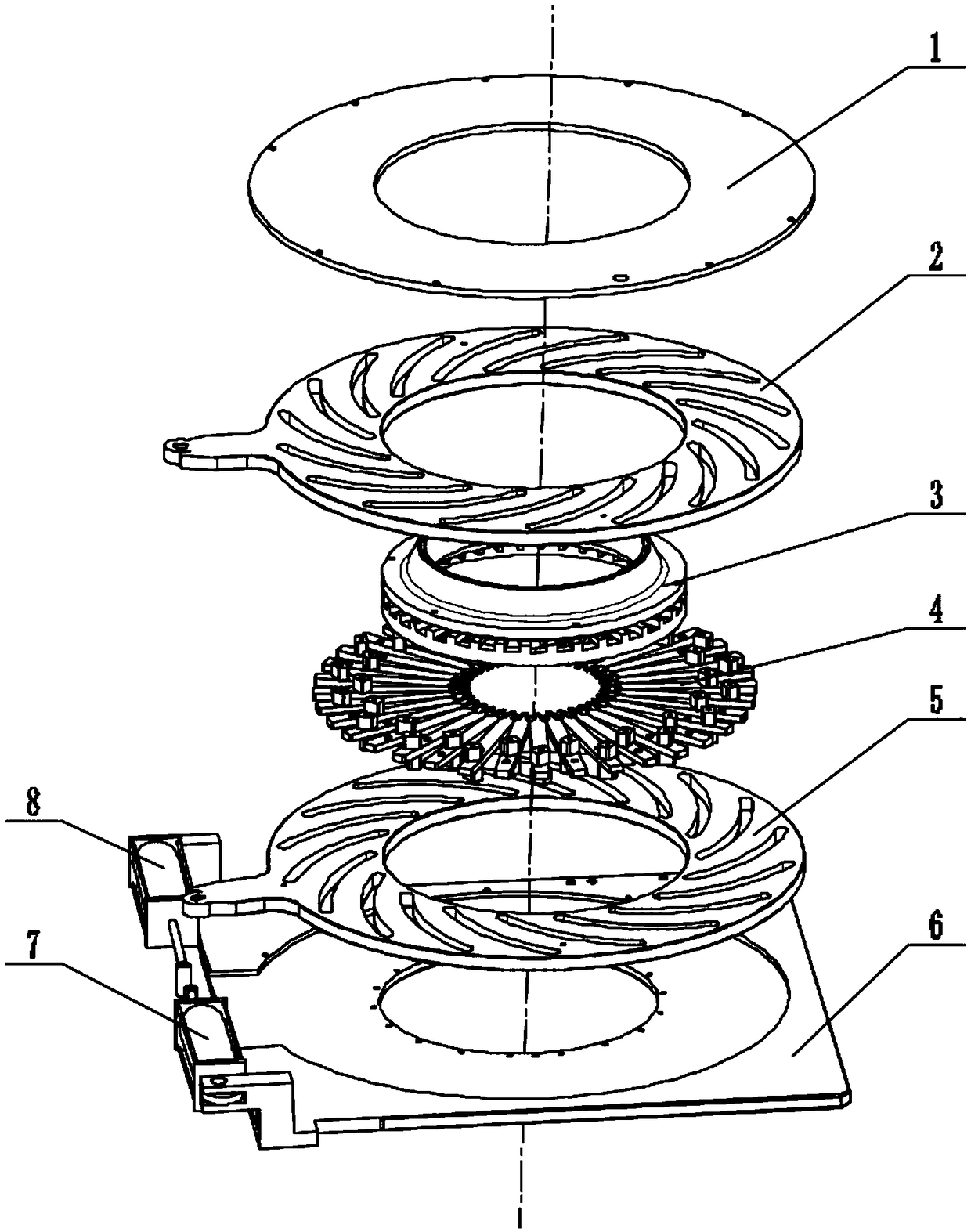
[0023] In the present invention, unless stated otherwise, the used orientation words such as "upper and lower" usually refer to figure 1 The upper and lower relationships shown in . "Inner and outer" refers to the internal and external relationship of the outline itself.

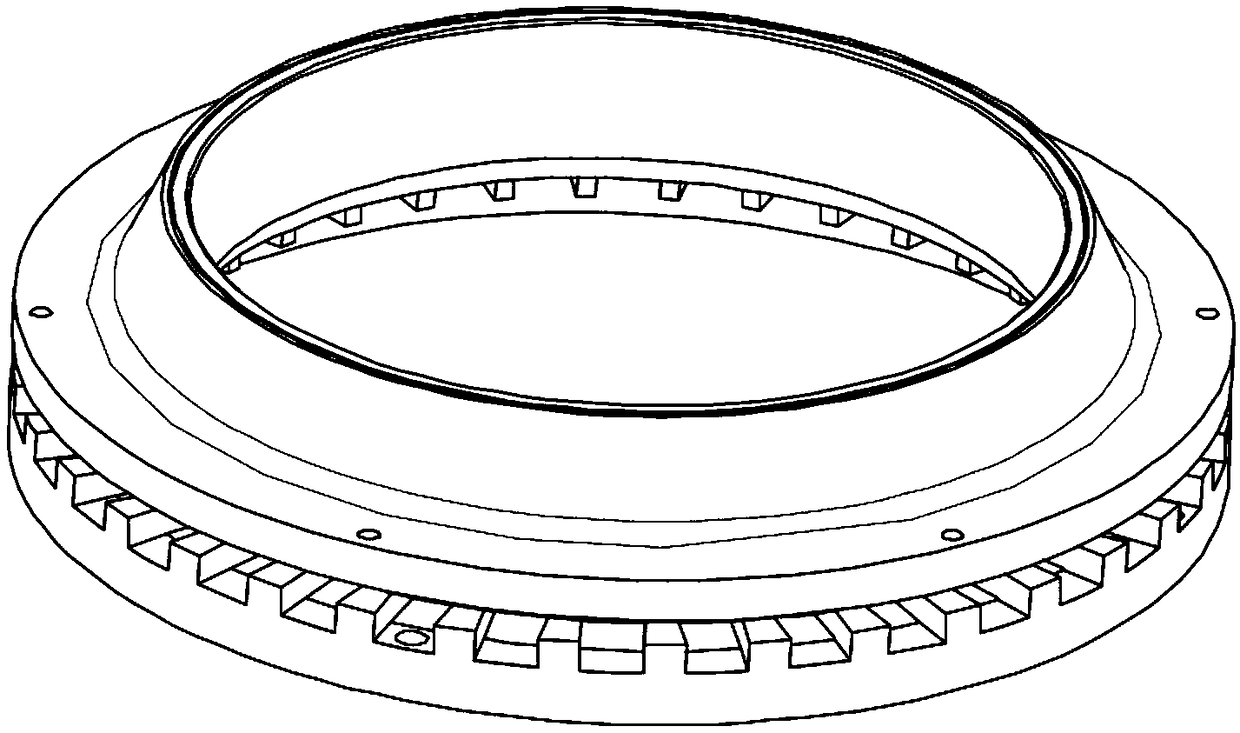
[0024] Such as figure 1 As shown, the present invention provides a thin-walled pipe clamping device, which includes a plurality of clamping heads 4, a central support 3, a first drive plate 2 and a second drive plate 5, the The central support 3 is ring-shaped, and is provided with a plurality of equally spaced limiting holes in the circumferential direction. The clamping head 4 is installe...


PUM


Abstract

The invention relates to the field of tool clamps, and discloses a clamping device for thin-walled pipes. The clamping device for thin-walled pipes comprises a plurality of clamping heads, a central support, a first driving disc and a second driving disc, wherein the central support is annular and is circumferentially provided with a plurality of limiting holes which are formed at equal spaces; the clamping heads are mounted in the limiting holes; the first driving disc and the second driving disc can be rotatably mounted on the central support; the clamping heads are positioned between the first driving disc and the second driving disc; a plurality of spiral sliding grooves are formed in the first driving disc and the second driving disc; the rotation direction of the sliding groove formed in the first driving disc is opposite to that of the sliding groove formed in the second driving disc; and sliding blocks are arranged on the two sides, close to the first driving disc and the second driving disc, of the clamping heads and can be slid along the sliding grooves. The clamping device for the thin-walled pipes disclosed by the invention has the advantages of high clamping speed, compact structure and uniform stress of the pipes.

Description

technical field [0001] The invention relates to a tooling fixture, in particular to a clamping device for thin-walled pipe fittings. Background technique [0002] The existing clamping fixture for pipe fittings is the same as the clamping cylinder, using a three-jaw chuck, including a bracket and an annular chuck, the chuck is fixed on the bracket, and at least three jaws are uniformly arranged on the chuck , the jaws are evenly distributed along the circumference, and are located on the same circle concentric with the annular chuck, each position where the jaws are connected to the chuck is provided with a connecting platform, on the connecting platform Two strip-shaped through holes are provided in parallel and symmetrical, respectively located on both sides of the jaws, screws pass through the strip-shaped through holes to fixedly connect the jaws to the chuck, the center of the end face of the chuck and the The line connecting the centers of the jaws is located at the r...

Claims


Application Information

Patent Timeline
IPC IPC(8): B23Q3/08
CPCB23Q3/064B23Q3/065B23Q3/08B23Q2703/04
Inventor 张帆张伟曾佑红肖勇平
Owner JIANGXI FG NEW ENERGY TRANSMISSION TECH CO LTD
Why Eureka
Try Eureka