Direction adjusting device of working shaft

A azimuth adjustment and working shaft technology, applied in the directions of transmission parts, belts/chains/gears, mechanical equipment, etc., can solve the problems of low adjustment efficiency, complex adjustment operation, poor accuracy, etc. The effect of eliminating the transmission gap of the screw countershaft

Pending Publication Date: 2019-03-22
SHANGHAI APPLIED TECHNOLOGIES COLLEGE +1
View PDF0 Cites 4 Cited by
  • Summary
  • Abstract
  • Description
  • Claims
  • Application Information

AI Technical Summary

Problems solved by technology

[0003] In the existing technology, there are deficiencies such as poor accuracy of shaft center position adjustment and axial clearance adjustment, low adjustment efficiency, and complicated adjustment operations.

Method used


Image

  • Direction adjusting device of working shaft
  • Direction adjusting device of working shaft
  • Direction adjusting device of working shaft

Examples


Embodiment Construction

[0033] The azimuth adjustment device of the working shaft proposed by the present invention will be further described in detail below in conjunction with the accompanying drawings and specific embodiments. Advantages and features of the present invention will be apparent from the following description and claims.

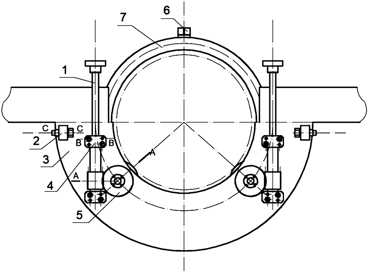
[0034] see figure 1 , the present embodiment provides an azimuth adjustment device for a working shaft, comprising:

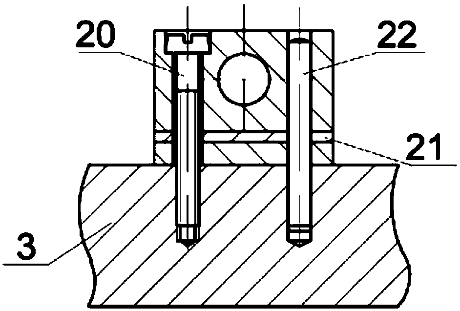
[0035] Slewing support 3;

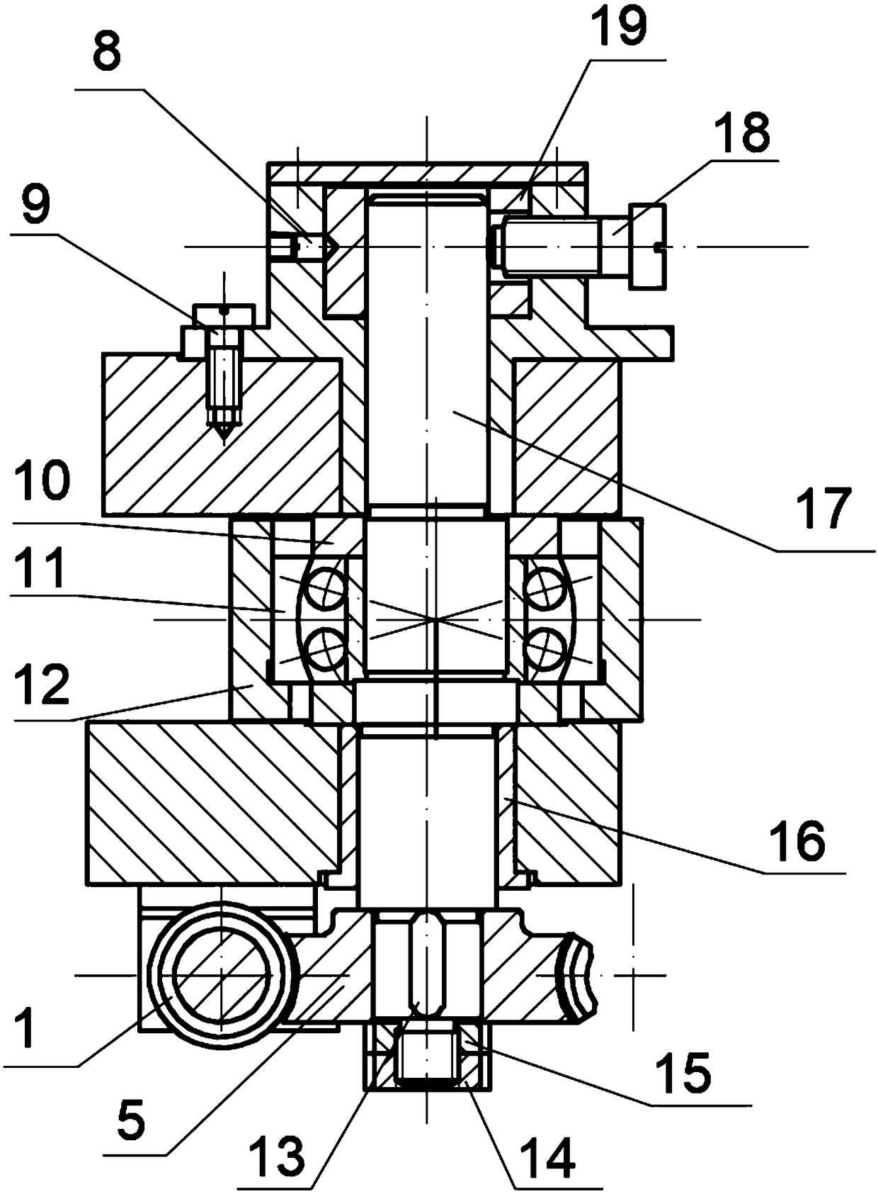
[0036] Up and down adjustment mechanism, the up and down adjustment mechanism is symmetrically arranged on the left and right sides of the slewing support 3, the up and down adjustment mechanism includes an adjustment wheel 12, an eccentric shaft 17 and a driving part, the driving part is fixed on the front end face of the slewing support 3, and the eccentric shaft 17 It includes a first shaft section and a second shaft section, the first shaft section and the second shaft section are fixedly connected, the central axis ...


PUM


Abstract

The invention discloses a direction adjusting device of a working shaft. The direction adjusting device comprises a rotary support, up-and-down adjusting mechanisms, left-and-right adjusting mechanisms and a gap adjusting assembly. The up-and-down adjusting mechanisms are symmetrically arranged on the left side and the right side in the rotary support. The up-and-down adjusting mechanisms compriseadjusting wheels, eccentric shafts and drive parts, wherein the drive parts drive the eccentric shafts to rotate, and the eccentric shafts drive the adjusting wheels to adjust the up-and-down position of the working shaft. The left-and-right adjusting mechanisms are symmetrically arranged on the end faces of the left side and the right side of the rotary support and used for adjusting the radialgaps between the working shaft and left-and-right relevant parts in order to adjust the left-and-right position of the working shaft. The gap adjusting assembly comprises multiple slip rings and locking parts, wherein the slip rings are arranged on the periphery of the working shaft, the slip rings are locked by the locking parts, the distances between the slip rings and the working shaft are fixedly limited, and the locked slip rings serve as reference parts and are used for calibrating and adjusting the gaps in the periphery of the working shaft. The direction adjusting device has the technical effects that the structure is simple, the adjusting operation saves labor and is rapid, and adjusting is precise.

Description

technical field [0001] The invention belongs to the technical field of power device installation, and in particular relates to an azimuth adjustment device of a working shaft. Background technique [0002] In the power plant, the cylinder assembly is a very important part. The high-power power plant unit is composed of high, medium and low pressure sub-cylinders. The high, medium and low pressure cylinders have their own working shafts. In the process of installation and maintenance, it is necessary to adjust the coaxiality of the axis line of the working shaft with the center line of the cylinder body, the center line of the partition inside the cylinder, and the center line of the steam seal. Adjust to the flow gap and the axial partition gap. [0003] In the prior art, there are deficiencies such as poor accuracy of shaft center position adjustment and axial gap adjustment, low adjustment efficiency, and complicated adjustment operations. Contents of the invention [...

Claims


Application Information

Patent Timeline
IPC IPC(8): F16H57/022
CPCF16H57/022F16H2057/0222
Inventor 张东民姚松骏朱景秋吴艳云王磊江尧夏平
Owner SHANGHAI APPLIED TECHNOLOGIES COLLEGE
Why Eureka
Try Eureka