An intelligent power module drive protection circuit
A technology for driving protection circuits and intelligent power modules, applied in the servo field, can solve problems such as signal lag, untimely alarm, and large space volume, and achieve the effects of low-latency detection, perfect functions, and reasonable space volume
- Summary
- Abstract
- Description
- Claims
- Application Information
AI Technical Summary
Problems solved by technology
Method used
Image

Examples
Embodiment 1
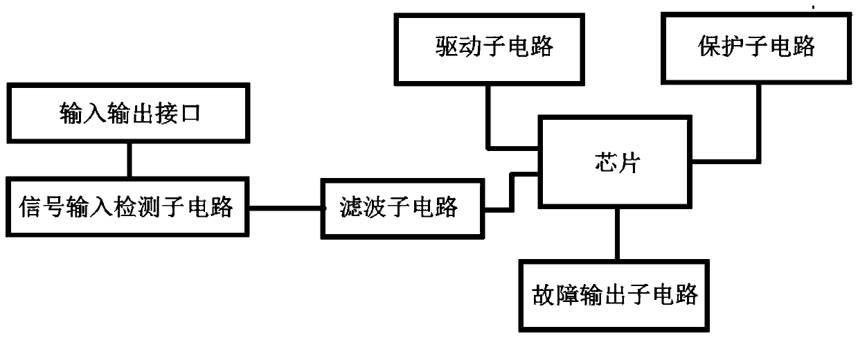
[0031] Such as figure 1 , The intelligent power module drive protection circuit includes: an input and output interface, a chip, a signal input detection sub-circuit, a filter sub-circuit, a drive sub-circuit, a protection sub-circuit and a fault output sub-circuit. Wherein, the signal input detection sub-circuit, filter sub-circuit, drive sub-circuit, protection sub-circuit and fault output sub-circuit are respectively connected to the chip through corresponding pins provided on the chip. The input and output interface is used to connect with the external controller to realize the signal transmission between the external controller and the intelligent power module drive protection circuit; the chip is used to detect the input signal and amplify the power, output the drive signal, and carry out the fault signal Output; the signal input detection sub-circuit is used to receive the control signal input by the external controller, preprocess the control signal to obtain the input...
Embodiment 2
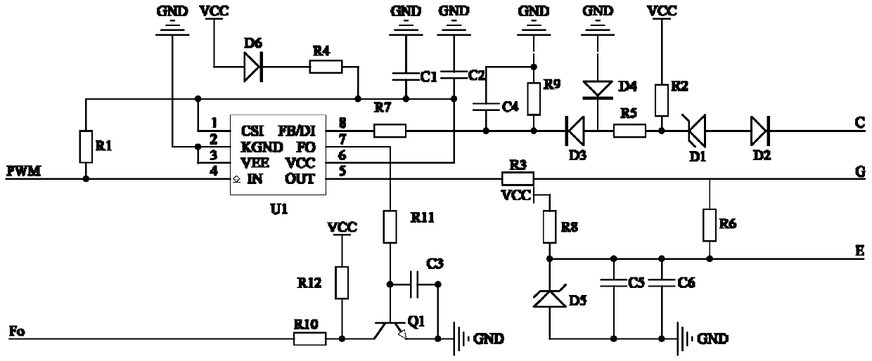
[0033] Such as figure 2 , in this embodiment, the pins provided on the chip at least include: overcurrent detection pin 1, input detection pin 4, drive signal output pin 5, power supply pin 6, fault output pin 7 and fault detection tube foot 8.
[0034] Preferably, the signal input detection sub-circuit may specifically include: a first resistor R1. Wherein, one end of the first resistor R1 is connected to the input and output interface, and the other end is connected to the input detection pin 4 on the chip to form a signal input detection sub-circuit to realize signal pull-up and have anti-interference ability.
[0035] Preferably, the filtering sub-circuit may specifically include: a first capacitor C1 and a second capacitor C2. Wherein, the first capacitor C1 and the second capacitor C2 are connected in parallel to the power supply pin and the overcurrent detection pin on the chip.
[0036] Preferably, the driving sub-circuit includes: a third resistor R3 and a sixth r...
Embodiment 3
[0044] The driving and protection circuit of the intelligent power module can be mainly composed of the driving chip U and its peripheral capacitors, resistors, diodes, voltage regulator tubes and other components, specifically including: the first resistor R1, the second resistor R2, and the third resistor R3 (drive resistor) , the fourth resistor R4 (current limiting resistor), the fifth resistor R5, the sixth resistor R6, the seventh resistor R7, the eighth resistor R8, the ninth resistor R9, the tenth resistor R10, the first capacitor C1, the second capacitor C2 , the third capacitor C3, the fourth capacitor C4, the fifth capacitor C5, the sixth capacitor C6, the first regulator tube D1, the second diode D2 (high voltage protection diode), the third diode D3, the fourth two Pole tube D4 and fifth voltage regulator tube D5 (providing the back pressure when the IGBT is turned off). Among them, the PWM signal input pin of the external controller and the fault signal port Fo a...
PUM
 Abstract
Description
Claims
Application Information
 - R&D
- Intellectual Property
- Life Sciences
- Materials
- Tech Scout
- Unparalleled Data Quality
- Higher Quality Content
- 60% Fewer Hallucinations
Browse by: Latest US Patents, China's latest patents, Technical Efficacy Thesaurus, Application Domain, Technology Topic, Popular Technical Reports.
© 2025 PatSnap. All rights reserved.Legal|Privacy policy|Modern Slavery Act Transparency Statement|Sitemap|About US| Contact US: help@patsnap.com