Examination bed for emergency departments

A departmental and emergency technology, applied in the direction of diagnosis, application, medical science, etc., can solve the problems of single function, the inability to store medical devices in the examination bed, and the inability to conveniently adjust the height of the bed board, so as to solve the problems of physical discomfort and unadjustable Effect

Inactive Publication Date: 2019-03-26
中国人民解放军陆军特色医学中心
View PDF9 Cites 0 Cited by
  • Summary
  • Abstract
  • Description
  • Claims
  • Application Information

AI Technical Summary

Problems solved by technology

[0002] The examination bed is a common device in the emergency room. It is used to make the patient lie on it to facilitate the doctor's examination. However, the existing examination bed has a simple structure and a single function. The existing examination bed cannot store medical devices, and the height of the bed board cannot be adjusted conveniently. , can not meet the needs of the current emergency room, in view of this, we propose a bed for the emergency department

Method used


Image

  • Examination bed for emergency departments
  • Examination bed for emergency departments
  • Examination bed for emergency departments

Examples


Embodiment 1

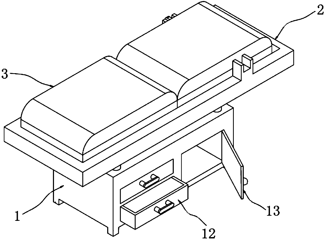
[0035] As the first embodiment of the present invention, a kind of examination bed for emergency department, such as figure 1 and image 3 As shown, including a bed body 3, a cabinet body 1 is provided below the bed body 3;

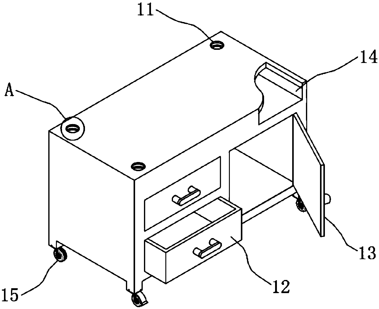
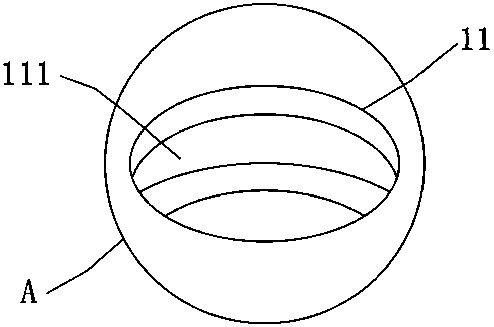
[0036] A rectangular cavity is provided on the cabinet body 1, a cavity 14 is provided in the top plate of the cabinet body 1, a through hole 11 communicating with the cavity 14 is respectively provided on the four corners of the upper surface of the cabinet body 1, and a hole wall of the through hole 11 is provided with There is a first annular groove 111, and three rectangular cavities are provided in the cabinet body 1, a drawer 12 is inserted in each of the two rectangular cavities, and a cabinet door 13 is hinged to the opening of the other rectangular cavity.

[0037] In this embodiment, a layer of rubber pad is tightly adhered to the bottom wall of the cavity 14, so as to achieve the effect of buffering and shock-absorbing the cabinet body 1 after...

Embodiment 2

[0039] As the second embodiment of the present invention, in order to achieve the effect of portable movement of the cabinet body 1, the inventors made improvements to the cabinet body 1, as a preferred embodiment, such as figure 2 As shown, four brake universal wheels 15 are installed at the bottom of the cabinet body 1 .

[0040] In this embodiment, since the bottom end of the cabinet body 1 is equipped with a brake universal wheel 15, when the baffle plate on the brake universal wheel 15 is released, the effect of portable movement of the cabinet body 1 can be realized.

Embodiment 3

[0042] As a third embodiment of the present invention, in order to achieve the effect of height adjustment of the bed body 3, the inventors made improvements to the bed body 3, as a preferred embodiment, such as Figure 4 to Figure 8 As shown, a lifting mechanism 2 is provided between the cabinet body 1 and the bed body 3. The lifting mechanism 2 includes a lifting plate 21. The bottom end of the lifting plate 21 is tightly welded with four screw rods 213, and the four four screw rods 213 can correspond to each other. Inserted coaxially into a through hole 11; the threaded pipe 23 is threadedly connected to the screw 213, and two annular protrusions 231 are tightly welded on the threaded pipe 23, and the annular protrusion 231 at the top is rotatably clamped on the first In the annular groove 111; belt 24 is closely surrounded between the four threaded pipes 23, and a turntable 25 is arranged in the middle of the belt 24. On the side wall of the turntable 25, an anti-slip pad 2...


PUM


Abstract

The invention relates to the technical field of beds, in particular to an examination bed for emergency departments. The examination bed includes a bed body, a cabinet is disposed under the bed body,a lifting mechanism is arranged between the cabinet and the bed body, the cabinet is equipped with a rectangular cavity, the top plate of the cabinet is provided with a cavity, four corners at the upper surface of the cabinet are respectively equipped with a through-hole communicated with the cavity, and the hole walls of the through-holes are equipped with first annular grooves. The lifting mechanism includes a lifting plate, four screw rods are closely welded to the bottom of the lifting plate, and can inserted into a through-hole coaxially in one-to-one correspondence. By means of the cabinet and the bed body, the examination bed provided by the invention realizes the effect of integrated cabinet and bed, also through the lifting mechanism, realizes height adjustment of the examinationbed, and in addition, through setting of heating wires in the bed board, realizes the effect of heating the examination bed, and solves the problem that patients can get a cold when lying in the examination bed and feel unwell.

Description

technical field [0001] The invention relates to the technical field of beds, in particular to a bed for emergency departments. Background technique [0002] The examination bed is a common device in the emergency room. It is used to make the patient lie on it to facilitate the doctor's examination. However, the existing examination bed has a simple structure and a single function. The existing examination bed cannot store medical devices, and the height of the bed board cannot be adjusted conveniently. , can not meet the current emergency room needs, in view of this, we propose a kind of emergency bed for emergency department. Contents of the invention [0003] The purpose of the present invention is to provide a bed for emergency department to solve the problems raised in the above background technology. [0004] To achieve the above object, the present invention provides the following technical solutions: [0005] A bed for emergency departments, including a bed body, ...

Claims


Application Information

Patent Timeline
Patent Type & Authority Applications(China)
IPC IPC(8): A61G13/06A61G13/08A61G13/10
CPCA61G13/06A61G13/08A61G13/10A61G2203/723A61G2210/90
Inventor 杨秀华罗家虹何荣芳李银燕马贞容
Owner 中国人民解放军陆军特色医学中心
Why Eureka
Try Eureka