
Trimming device for terminals

A cutting and terminal technology, applied in the direction of coating, etc., can solve the problems of terminal product deformation, low efficiency, poor quality, etc.

Pending Publication Date: 2019-03-26
上海天檀电子科技有限公司
View PDF4 Cites 4 Cited by
  • Summary
  • Abstract
  • Description
  • Claims
  • Application Information

AI Technical Summary

Problems solved by technology

In the traditional production process, the terminal products are generally removed from the tape by manual pulling, but this method is not only inefficient, but also easily leads to deformation of the terminal products and poor quality
There are also some cutting machines on the market that can automatically separate the terminal products from the strip, but these cutting machines are only suitable for a certain type of terminal products, and the applicability is poor

Method used


Image

  • Trimming device for terminals
  • Trimming device for terminals
  • Trimming device for terminals

Examples


Embodiment Construction

[0022] Specific embodiments of the present invention will be described in detail below in conjunction with the accompanying drawings. It should be understood that the specific embodiments described here are only used to illustrate and explain the present invention, and are not intended to limit the present invention.

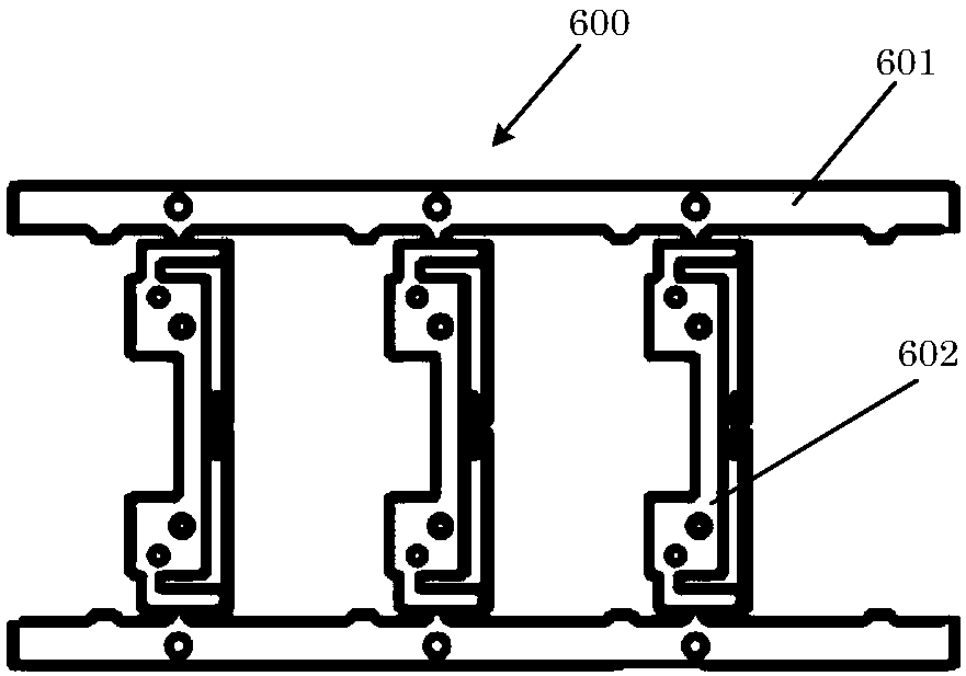
[0023] figure 1 A schematic structural view of the terminal strip is shown. like figure 1 As shown, in the present invention, the terminal product 602 and the strip 601 before being separated are called the terminal strip 600 together.

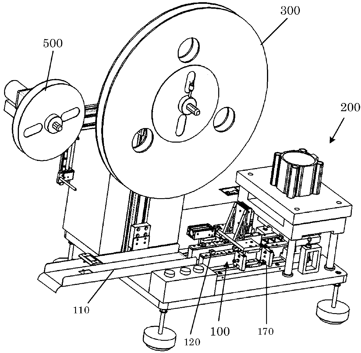
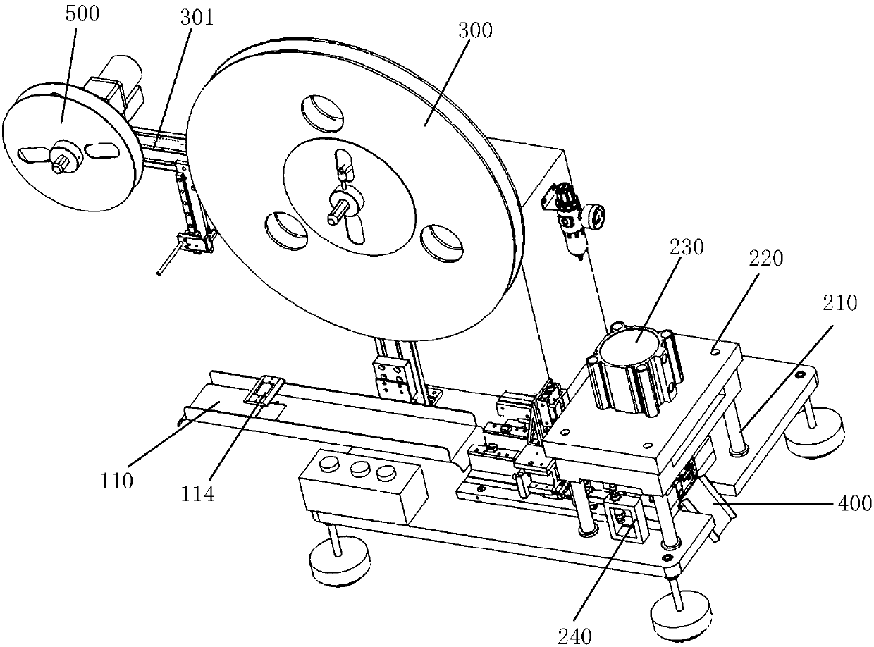
[0024] figure 2 and image 3 It is a structural schematic diagram of a terminal cutting device according to an embodiment of the present invention. like figure 2 and image 3 As shown, in one embodiment of the present invention, a terminal cutting device is provided. The terminal cutting device may include a feeding mechanism 100, a cutting mechanism 200 and a terminal feeding tray 300. The feeding mechanism 100 include...


PUM


Abstract

The invention relates to the technical field of terminal trimming and discloses a trimming device for terminals. The trimming device for the terminals comprises a feeding mechanism, a trimming mechanism and a terminal feeding disk. The feeding mechanism comprises a feeding groove with width adjustable and a locating assembly matched with the width of the feeding groove. The feeding groove and thelocating assembly are used for limiting movement locus of a terminal material belt. According to the trimming device for the terminals, automatic and continuous trimming can be conducted on the terminal material belt, and in addition, the trimming device for the terminals is applicable to terminal products of multiple models.

Description

technical field [0001] The present invention relates to the technical field of terminal cutting, in particular to a terminal cutting device. Background technique [0002] Due to factors such as manufacturing process and characteristic heterogeneity, terminal products need to be produced in the form of strips. Before the terminal product is embedded in the mold for injection molding production, the terminal product needs to be separated from the strip. In the traditional production process, the terminal products are generally removed from the tape by manual pulling, but this method is not only inefficient, but also easily leads to deformation of the terminal products and poor quality. There are also some cutting machines on the market that can automatically separate the terminal product from the strip, but these cutting machines are only suitable for a certain type of terminal product, and the applicability is poor. Contents of the invention [0003] The purpose of the pr...

Claims


Application Information

Patent Timeline
Patent Type & Authority Applications(China)
IPC IPC(8): B29C45/14
CPCB29C45/14221
Inventor 邹建黄成
Owner 上海天檀电子科技有限公司
Learn More