
Circumferential locking mechanism, battery locking device comprising same, power battery pack and vehicle

A technology for power battery packs and locking devices, which is applied in the direction of electric power devices, power devices, vehicle components, etc., can solve problems such as the inability to maintain screw torque, achieve firm joints, and improve the effect of tolerance

Inactive Publication Date: 2019-03-26
NIO ANHUI HLDG CO LTD
View PDF8 Cites 6 Cited by
  • Summary
  • Abstract
  • Description
  • Claims
  • Application Information

AI Technical Summary

Problems solved by technology

In this application, there is also the situation that the engagement position of the pin 301 and the groove 101 is inconsistent with the engagement position of the pin 500 and the groove 205; in order to avoid this situation, threaded connections are used in the prior art to replace the pin 301 and the groove 101, but still Has the disadvantage of not being able to maintain an approximately constant screwing torque

Method used


Image

  • Circumferential locking mechanism, battery locking device comprising same, power battery pack and vehicle
  • Circumferential locking mechanism, battery locking device comprising same, power battery pack and vehicle

Examples


Embodiment Construction

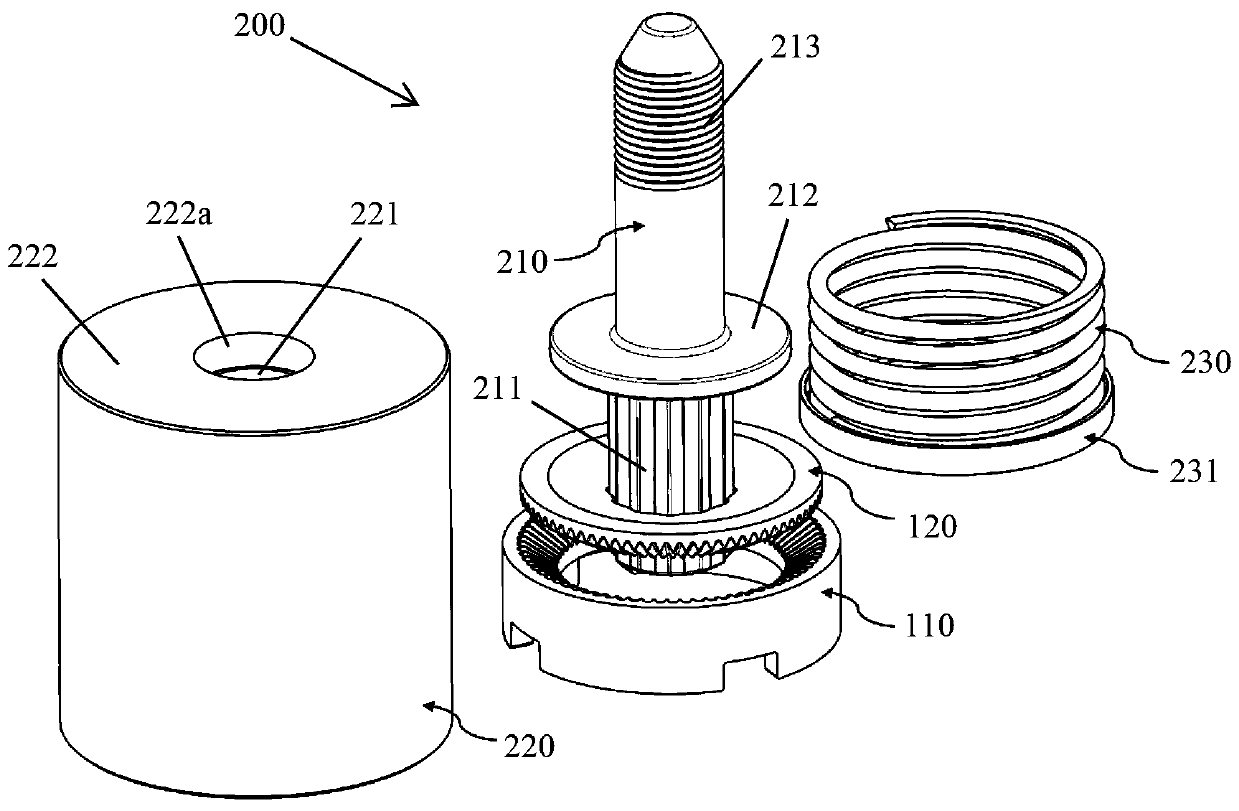
[0025] Specific embodiments of the present application will be described in detail below with reference to the accompanying drawings. In the drawings, the same reference numerals represent the same or corresponding technical features.

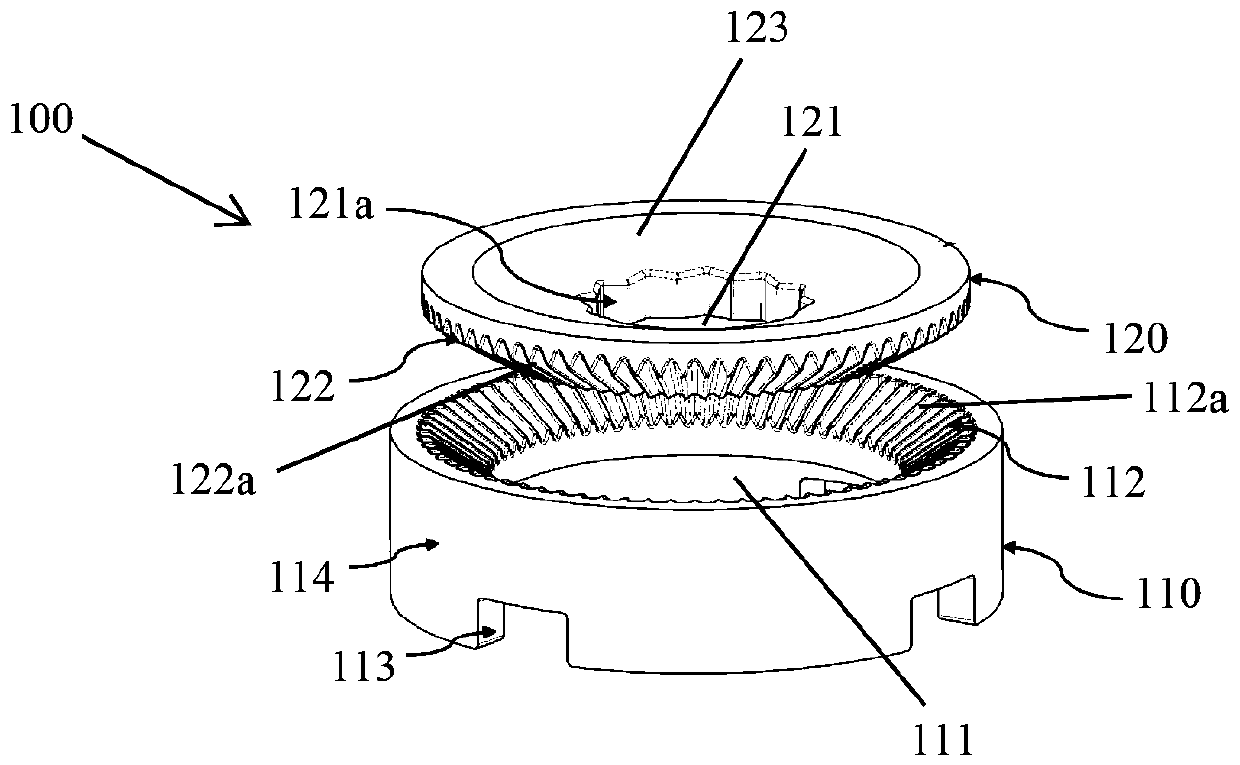
[0026] figure 1 is a schematic perspective view of an embodiment of the circumferential locking mechanism according to the present application. The circumferential locking mechanism 100 in the illustrated embodiment includes a first component 110 and a second component 120 . Wherein, the first part 110 includes a first through hole 111 and an inner ring gear 112 arranged around the first through hole 111, the inner ring gear 112 has internal helical teeth 112a distributed along the inner circumference; the second part 120 includes a second through hole 121 and the outer gear ring 122 and tightening sleeve 123 arranged around the second through hole 121, the outer gear ring 122 has external helical teeth 122a distributed along the outer circum...


PUM


Abstract

The invention provides a circumferential locking mechanism, a battery locking device comprising the same, a power battery pack and a vehicle. The circumferential locking mechanism comprises a first component and a second component; the first component comprises a first through hole and an inner gear ring arranged around the first through hole, and the inner gear ring is provided with inner obliqueteeth distributed along the inner circumference; the second component comprises a second through hole, an outer gear ring and a tightening sleeve; the outer gear ring and the tightening sleeve are arranged around the second through hole; the outer gear ring is provided with outer oblique teeth distributed along the outer circumference; the tightening sleeve is fixed to the inner side of the outergear ring in an embedded mode, and the inner oblique teeth are suitable for being connected with the outer oblique teeth. According to the invention, the tolerance degree of the first component and the second component in the joint process is improved through cooperation of the oblique teeth on the inner gear ring and the outer gear ring; after joint is completed, locking force with enough strength can be provided in the radial direction and the circumferential direction, and it is guaranteed that the first component and the second component can be firmly jointed.

Description

technical field [0001] The present application relates to the technical field of circumferential anti-loosening and locking of components; in particular, the present application relates to a circumferential locking mechanism and a battery locking device using the same. Background technique [0002] It is often encountered in the prior art that the relative rotation of two components needs to be limited. [0003] For example, in screw connection, how to ensure the constant pre-tightening force of the connection is a difficult problem in the industry. Currently commonly used anti-loosening structures include providing a multi-tooth anti-loosening structure or a pin-slot structure on an easily movable threaded part. This structure can only provide limited locking positioning. With these technologies, when the screwing torque reaches a predetermined value, if the teeth or grooves cannot engage at the corresponding angle, there is still a risk of loosening of the threaded parts ...

Claims


Application Information

Patent Timeline
Patent Type & Authority Applications(China)
IPC IPC(8): B60K1/04
CPCB60K1/04
Inventor 袁春萍林海岩李楠田小涛
Owner NIO ANHUI HLDG CO LTD
Learn More