Method for machining small-cutting-in roughing-feed integral impeller rough slot

A technology of integral impeller and processing method, applied in metal processing equipment, manufacturing tools, details of milling machine equipment, etc., can solve problems such as prolonging processing time

Inactive Publication Date: 2013-06-19
SHENYANG LIMING AERO-ENGINE GROUP CORPORATION
View PDF6 Cites 6 Cited by
  • Summary
  • Abstract
  • Description
  • Claims
  • Application Information

AI Technical Summary

Problems solved by technology

Extended processing time due to conventional processing methods requiring at least two operations

Method used


Image

  • Method for machining small-cutting-in roughing-feed integral impeller rough slot
  • Method for machining small-cutting-in roughing-feed integral impeller rough slot
  • Method for machining small-cutting-in roughing-feed integral impeller rough slot

Examples


Embodiment 1

[0029] A rough grooving method for integral impellers with small depth of cut and high feed: use a special flying saucer milling cutter to process deep cavity grooves with a depth of 3-5 times the cutter radius, each cut depth is 1-4.5mm, and each tooth The dosage is 0.5-1mm;

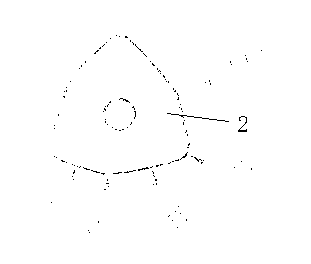
[0030] The special flying saucer milling cutter meets the following requirements: it is composed of a cutter bar 1, a blade 2, and a fixing screw 3, and the blade 2 is positioned at the front end of the cutter bar 1 and is fixed on the cutter bar 1 by the fixing screw 3; The flying saucer milling cutter has three heads, the blade 2 has three pieces, and the blade 2 is triangular. Specifically, the main body profile of the blade 2 is a triangle, such as image 3 shown.

[0031]

[0032] In the rough grooving processing method of the integral impeller with small depth of cut and high feed, the depth of each cut is 1.5-4 mm, and the feed rate per tooth is preferably 0.55-0.8 mm.

[0033] In the rough g...

Embodiment 2

[0039] This embodiment is specifically implemented on the basis of embodiment 1, and the specific requirements different from embodiment 1 are as follows:

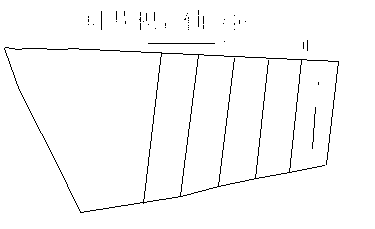
[0040] Titanium alloy deep cavity processing: The workpiece to be processed is an axial-flow integral impeller, and the processing part is the cavity between the blades. The processing depth is 170mm, and the tool is processed by a special milling cutter with a diameter of 40mm. The processing parameters are as follows: the cutting line speed is 63m / min, the feed rate per tooth is 0.5mm / tooth, the calculated tool speed is 500 rpm, the feed rate is 750mm / min, and the depth of cut for each layer is 1.2mm. The toolpath of the tool can be found in the appendix Figure 7 . Due to the large feed rate per tooth, the machining cooling method has a great impact on tool life. In order to prolong tool life, it must be equipped with an internal powerful cooling system.

[0041]

Embodiment 3

[0043] This embodiment is specifically implemented on the basis of embodiment 1, and the specific requirements different from embodiment 1 are as follows:

[0044] Die steel deep cavity processing: the workpiece to be processed is an extrusion die, the processing part is a cavity, the processing depth is 130mm, and the diameter of the tool is 40mm. Special milling cutter is used for processing. Processing example see attached Figure 8.

[0045] The processing parameters are as follows: the cutting line speed is 80m / min, the feed rate per tooth is 0.7mm / tooth, the calculated tool speed is 700 rpm, the feed rate is 140mm / min, and the depth of cut for each layer is 1.0mm. Due to the large feed rate per tooth, the machining cooling method has a great impact on tool life. In order to prolong tool life, it must be equipped with an internal powerful cooling system.


PUM


Abstract

A method for machining a small-cutting-depth roughing-feed integral impeller rough slot is characterized in that a special-purpose flying disc milling cutter is used for machining a deep-cavity groove with the depth being 3-5 times of the semi-diameter of the cutter, each cutting-in is 1-4.5mm, and feed per tooth is 0.5-1mm. The special-purpose flying disc milling cutter meets the following requirements: the special-purpose flying disc milling cutter is composed of a cutter rod (1), cutter blades (2), and a fixing screw (3), wherein the cutter blades (2) are placed at the front end of the cutter rod (1) and fixed on the cutter rod (1) through the fixing screw (3); and the special-purpose flying disc milling cutter is provided with three heads, the number of the cutter blades (2) is three, and the cutter blades are in a triangular shape. In the method for machining the small-cutting-in roughing-feed integral impeller rough slot, service life of the cutter is long, and for a cutter with the diameter of 40mm, the cutting size to be kept in 400cm<2> is appropriate. The feed per tooth is obviously large, component force of cutting force borne by the cutter blades can reach above 90% in the axial direction, and the service life of the cutter is long.

Description

[0001] technical field [0002] The invention relates to the technical field of mechanical manufacturing, and in particular provides a rough grooving processing method for an integral impeller with small cutting depth and high feed. Background technique [0003] The overall impeller processing technology is the key technology of advanced aero-engines. Due to the limitation of special processing technology on material properties and processing accuracy requirements, machining is still a widely used processing method. [0004] In the processing of the integral impeller, the blade surface is a complex free-form surface, and the blade part cannot be forged directly. Therefore, the blank of the integral impeller is mostly an integral forging, which causes the material removal rate of the integral impeller to increase during the processing process. The maximum removal rate can be Up to 93% or more. [0005] At present, the processing methods of integral impellers mostly adopt dri...

Claims


Application Information

Patent Timeline
Patent Type & Authority Applications(China)
IPC IPC(8): B23C3/18B23C5/10
Inventor 岳召启李丹张积瑜陈亚莉
Owner SHENYANG LIMING AERO-ENGINE GROUP CORPORATION
Why Eureka
Try Eureka