A rotating assembly and steering gear connection mechanism

A technology of rotating components and connecting mechanisms, which is applied in the direction of motor vehicles, mechanical equipment, bearing components, etc., can solve problems such as poor running accuracy, achieve the effects of no loss of torque, avoid deflection, and ensure installation accuracy and working accuracy

Active Publication Date: 2020-09-15
BEIJING SPACE TECH RES & TEST CENT
View PDF6 Cites 0 Cited by
  • Summary
  • Abstract
  • Description
  • Claims
  • Application Information

AI Technical Summary

Problems solved by technology

[0004] The purpose of the present invention is to provide a rotating assembly and steering gear connection mechanism to solve the problem of poor running accuracy of existing structures

Method used


Image

  • A rotating assembly and steering gear connection mechanism
  • A rotating assembly and steering gear connection mechanism
  • A rotating assembly and steering gear connection mechanism

Examples


Embodiment approach

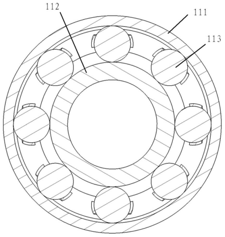
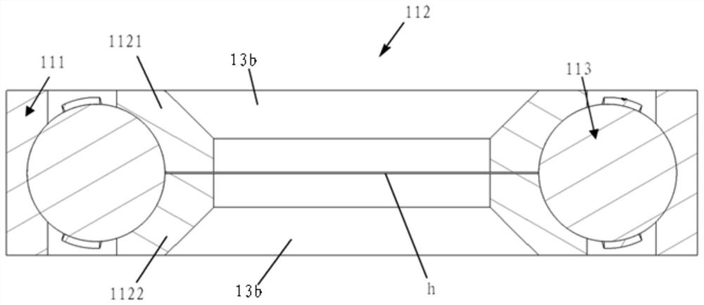
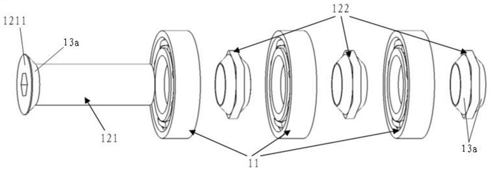
[0035] to combine figure 1 and figure 2 As shown, according to an embodiment of the present invention, a rotating assembly of the present invention includes: a bearing 11 and a locking member 12 . In this embodiment, the locking member 12 and the bearing 11 are coaxially connected to each other. In this embodiment, the bearing 11 includes a rotating outer ring 111 , a rotating inner ring 112 , and a rolling assembly 113 located between the rotating outer ring 111 and the rotating inner ring 112 . The rolling assembly 113 is clamped between the rotating outer ring 111 and the rotating inner ring 112 to ensure the relative rotation of the rotating outer ring 111 and the rotating inner ring 112 . see figure 2 As shown, in this embodiment, the rotating inner ring 112 includes a first inner ring portion 1121 and a second inner ring portion 1122 . The first inner ring portion 1121 and the second inner ring portion 1122 are arranged symmetrically to each other. Groove structur...


PUM


Abstract

The invention relates to a rotating component and a steering gear connecting mechanism. The rotating component comprises a bearing (11) and a locking component (12), wherein the bearing (11) comprisesa rotating outer ring (111), a rotating inner ring (112), and a rolling component (113) located between the rotating outer ring (111) and the rotating inner ring (112); the rotating inner ring (112)comprises a first inner ring portion (1121) and a second inner ring portion (1122); and the locking component (12) is coaxial with the rotating inner ring (112) and is used for locking the first innerring portion (1121) and the second inner ring portion ( 1122). By adopting the rotating component, the rotating inner ring of the rotating component can eliminate the free gap of the mechanism underthe locking action of the locking component, so that when the torque of the steering gear connecting mechanism is transmitted to a rudder shaft end, the torque is not delayed and not lost, and meanwhile, the steering gear connecting mechanism has good later-period maintainability and curing property.

Description

technical field [0001] The invention relates to the field of mechanical design, in particular to a rotating assembly and a steering gear connection mechanism. Background technique [0002] A hypersonic vehicle is a winged or wingless aircraft that flies faster than five times the speed of sound, such as aircraft, missiles, and artillery shells. Among them, the hypersonic winged aircraft is the most technically difficult. Due to the high flight speed of hypersonic aircraft, in order to ensure that the engine thrust can overcome the high-speed flight resistance, the aircraft is usually designed in a flat shape, which will cause serious problems such as very limited space inside the aircraft and limited equipment installation methods. Therefore, the connection between the steering gear and the rudder shaft of a hypersonic vehicle is usually realized in the form of a linkage mechanism. [0003] The general connecting rod structure adopts the form of ordinary bearing plus conne...

Claims


Application Information

Patent Timeline
Patent Type & Authority Patents(China)
IPC IPC(8): B64C13/38F16C19/02F16C33/60
CPCB64C13/38F16C19/02F16C33/60F16C2326/43
Inventor 刘瑜乔宇航石泳左光张志贤
Owner BEIJING SPACE TECH RES & TEST CENT
Why Eureka
Try Eureka