Printer with printing paper convenient to replace

A technology of printer and printing paper, which is applied in the direction of object separation, pile separation, thin material processing, etc., can solve the problems of mutual mixing, smudges, complicated and chaotic printing process, etc.

Active Publication Date: 2019-03-26
河南京硕信息科技有限公司
View PDF5 Cites 1 Cited by
  • Summary
  • Abstract
  • Description
  • Claims
  • Application Information

AI Technical Summary

Problems solved by technology

The existing paper trays have the following problems: 1) In the existing paper trays, the operator artificially adds printing paper to the paper tray when the printing paper is expected to be used up or after the printing paper has been used up. If there were many documents to be printed at that time and the documents were urgently needed, it would be a waste of time to artificially find the printing paper and then add the printing paper, resulting in a slow printing progress; The importance of choosing different printing paper, for example, when printing contracts with other companies, new printing paper will be used, and when printing informal documents used by internal personnel, poor paper and stained paper will be used. Or printing paper that has been used once but will not affect its reuse
When using the existing paper tray, it is necessary to slide the tray out and replace the original printing paper inside, and then slide the tray into the printer. If there are many people printing, it is easy to need The situation of constantly replacing the paper in the paper tray causes the printing process to be complicated and confusing, and reduces the printing efficiency; 3) The existing paper tray cannot classify brand new printing paper and used printing paper, so the two When different kinds of printing paper are constantly replaced, it is easy to be mixed with each other, and it is also easy to mix with the printed documents

Method used


Image

  • Printer with printing paper convenient to replace
  • Printer with printing paper convenient to replace
  • Printer with printing paper convenient to replace

Examples


Embodiment Construction

[0017] The following is further described in detail through specific implementation methods:

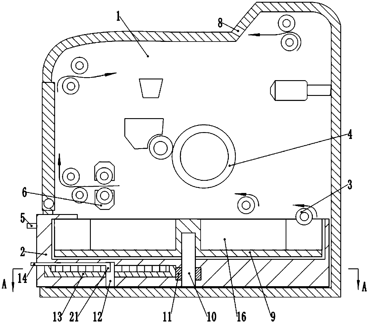
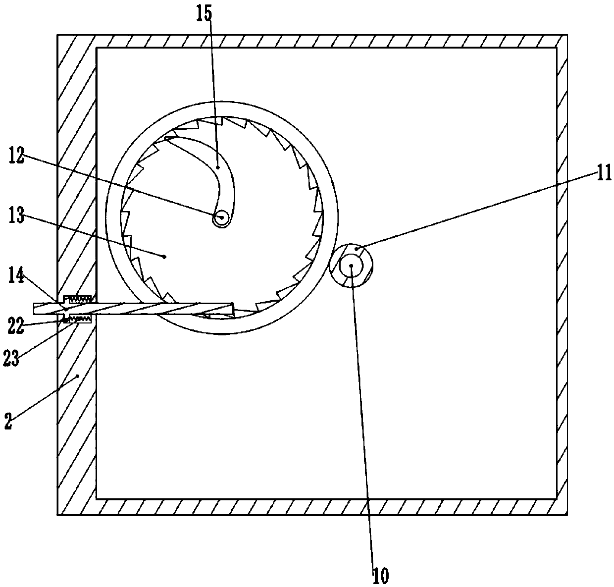
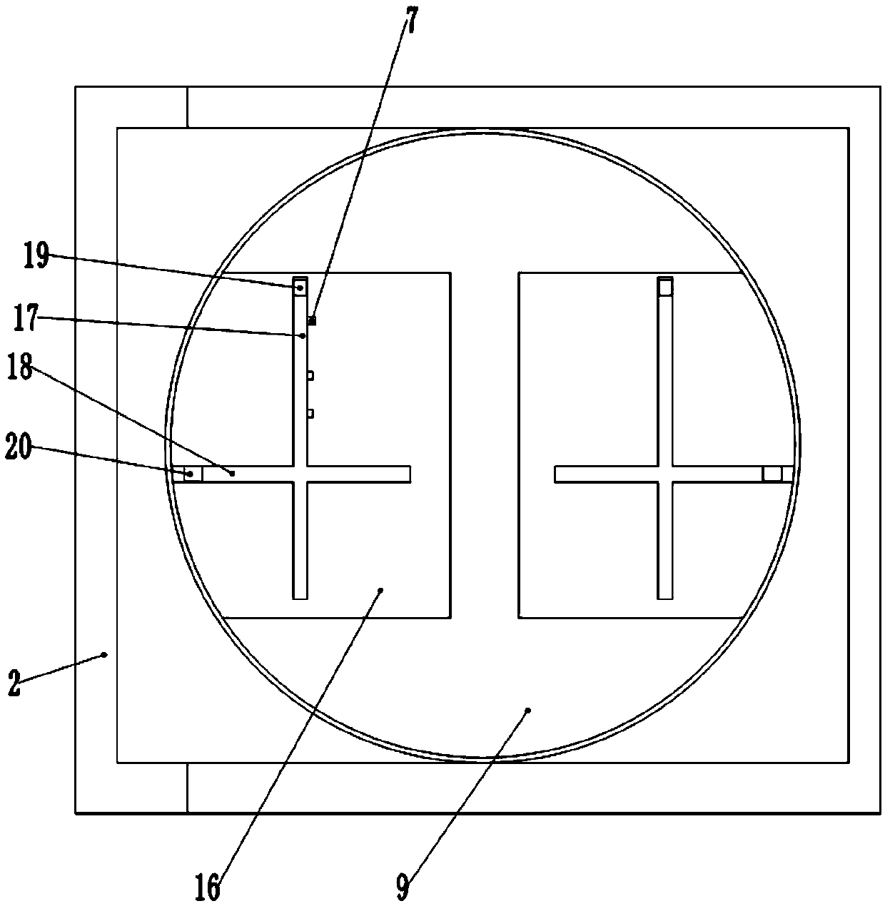
[0018] The reference signs in the accompanying drawings of the specification include: printer body 1, paper tray 2, paper pick-up roller 3, photosensitive drum unit 4, handle 5, fuser 6, limit slot 7, printing paper output port 8, rotating disc 9 , rotating shaft 10, gear 11, ratchet rotating shaft 12, internal gear ratchet 13, driving rod 14, positioning rod 15, paper slot 16, first slide rail 17, second slide rail 18, first limit block 19, the first Two limit block 20, push block 21, protrusion 22, stage clip 23.

[0019] The embodiment is basically as attached figure 1 As shown: the office printer includes a printer body 1 and a paper tray 2 , the paper tray 2 is slidably connected in the printer body 1 , and a roller is rotatably connected between the paper tray 2 and the printer body 1 . A paper pick-up roller 3 is arranged above the right end of the paper tray 2, and the pape...


PUM


Abstract

The invention relates to the technical field of printing equipment and particularly discloses a printer with printing paper convenient to replace. The printer comprises a printer body and a paper containing disc. The paper containing disc is connected into the printer body in a sliding mode and rotationally connected with a rotary disc. At least two paper grooves are formed in the rotary disc in the radial direction. A driving mechanism is arranged in the paper containing disc and comprises a gear, a rotary shaft and an inner tooth ratchet wheel. The gear is located below the rotary disc, andthe gear and the rotary disc are coaxially and fixedly arranged on the rotary shaft. The inner tooth ratchet wheel is rotationally arranged in the paper containing disc, and the outer circumferentialsurface of the inner tooth ratchet wheel is engaged with the gear. A driving rod used for driving the inner tooth ratchet wheel is connected into the paper containing disc in a sliding mode. One end of the driving rod stretches out of the paper containing disc, a push block used for driving the inner tooth ratchet wheel is fixedly arranged at the other end of the driving rod, and the middle of thedriving rod is horizontally hinged to the paper containing disc. By adopting the scheme, the purpose that the printing paper is fast replaced during printing can be achieved.

Description

technical field [0001] The invention relates to the technical field of printing equipment, and specifically discloses a structure of a paper tray for a printer. Background technique [0002] Printers are commonly used equipment in offices, and the paper trays in existing printers are generally plastic baskets that are slidably connected to the printer and are used to store printing paper. When the printing paper is used up, just slide the paper tray out of the printer, put neatly stacked printing papers into the paper tray, and then slide the paper tray into the printer. The existing paper trays have the following problems: 1) In the existing paper trays, the operator artificially adds printing paper to the paper tray when the printing paper is expected to be used up or after the printing paper has been used up. If there were many documents to be printed at that time and the documents were urgently needed, it would be a waste of time to artificially find the printing paper ...

Claims


Application Information

Patent Timeline
Patent Type & Authority Applications(China)
IPC IPC(8): B65H1/28
CPCB65H1/28B65H2701/1131
Inventor 陈民江
Owner 河南京硕信息科技有限公司
Why Eureka
Try Eureka