Oil and gas processing device performance testing method

A technology of oil and gas processing and testing methods, applied in the direction of measuring devices, testing of machine/structural components, instruments, etc., can solve problems such as lack of performance testing environment and systems

Active Publication Date: 2019-07-16
CHINA PETROLEUM & CHEM CORP +1
View PDF6 Cites 0 Cited by
  • Summary
  • Abstract
  • Description
  • Claims
  • Application Information

AI Technical Summary

Problems solved by technology

[0004] The technical problem to be solved by the present invention is the lack of an effective performance testing environment and system in the prior

Method used


Image

  • Oil and gas processing device performance testing method
  • Oil and gas processing device performance testing method

Examples


Embodiment 1

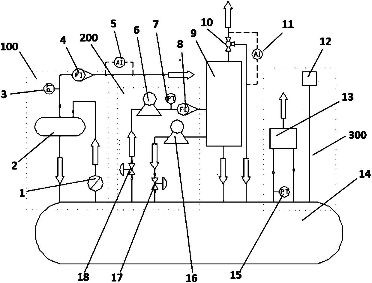
[0022] A method for testing the performance of an oil and gas treatment device, such as figure 1 As shown, the oil and gas treatment device performance test system is used for device performance testing. The system includes buried oil tanks, gas supply systems, oil supply systems, and pressure reduction systems. The tanks are respectively connected with the gas supply system, oil supply system, and pressure-reducing system. The oil supply system is connected with the device to be tested. The oil supply system includes an oil inlet pump and an oil outlet pump. The oil outlet is connected, and the depressurization system includes an oil gas treatment device and a pressure vacuum valve. The oil gas treatment device is equipped with an inlet pipeline and an outlet pipeline, all of which are connected with the buried oil tank.

[0023] The oil supply system (200) includes an oil inlet pump (6), an oil return pump (16) and related pipelines, instruments and valves. The main functio...

Embodiment 2

[0031] A method for testing the performance of an oil and gas treatment device, such as figure 1 As shown, the oil and gas treatment device performance test system is used for device performance testing. The system includes buried oil tanks, gas supply systems, oil supply systems, and pressure reduction systems. The tanks are respectively connected with the gas supply system, oil supply system, and pressure-reducing system. The oil supply system is connected with the device to be tested. The oil supply system includes an oil inlet pump and an oil outlet pump. The oil outlet is connected, and the depressurization system includes an oil gas treatment device and a pressure vacuum valve. The oil gas treatment device is equipped with an inlet pipeline and an outlet pipeline, all of which are connected with the buried oil tank.

[0032] The oil supply system (200) includes an oil inlet pump (6), an oil return pump (16) and related pipelines, instruments and valves. The main functio...

Embodiment 3

[0040] A method for testing the performance of an oil and gas treatment device, such as figure 1 As shown, the oil and gas treatment device performance test system is used for device performance testing. The system includes buried oil tanks, gas supply systems, oil supply systems, and pressure reduction systems. The tanks are respectively connected with the gas supply system, oil supply system, and pressure-reducing system. The oil supply system is connected with the device to be tested. The oil supply system includes an oil inlet pump and an oil outlet pump. The oil outlet is connected, and the depressurization system includes an oil gas treatment device and a pressure vacuum valve. The oil gas treatment device is equipped with an inlet pipeline and an outlet pipeline, all of which are connected with the buried oil tank.

[0041] The oil supply system (200) includes an oil inlet pump (6), an oil return pump (16) and related pipelines, instruments and valves. The main functio...


PUM


Abstract

The invention relates to an oil and gas processing device performance testing method, mainly to solve the problem of lacking an effective performance testing environment and a system in the prior art.Through adopting an oil and gas processing device performance testing method, an oil and gas processing device performance testing system is adopted for device performance testing. The system includes a buried oil tank, a gas supply system, an oil supply system and a pressure reduction system, wherein the gas supply system comprises a power pump and a ground storage tank; the buried oil tank is respectively connected with the gas supply system, the oil supply system and the pressure reduction system; the oil supply system is connected with a to-be-tested device; the oil supply system includesan oil inlet pump and an oil outlet pump; the oil inlet pump is connected with the entrance of the to-be-tested device; the oil outlet pump is connected with the exit of the to-be-tested device; thepressure reduction system comprises an oil and gas processing device and a pressure vacuum valve; and the oil and gas processing device is provided with an entrance pipeline and an exit pipeline whichare both connected with the buried oil tank. The technical scheme can well solve the above problem and can be applied to oil and gas processing device performance testing.

Description

technical field [0001] The invention relates to a method for testing the performance of an oil and gas processing device. Background technique [0002] In the past 20 years, my country is in a period of rapid economic development, and the consumption of industrial energy is increasing day by day. The oil and gas volatilized in the process of transportation, storage and transfer of a large amount of refined oil not only cause waste of resources, but also pollute the environment. In response to this phenomenon, my country promulgated a number of standards such as GB20950 "Emission Standards of Air Pollutants for Oil Storage Depots" and GB20952 "Emission Standards of Air Pollutants for Gas Stations" in 2007, requiring the oil and gas volatilized in each link of refined oil transportation and transfer operations to be carried out. Recycling treatment, thus promoting the development of oil and gas recovery treatment technology. At present, oil and gas treatment devices are mainly...

Claims


Application Information

Patent Timeline
IPC IPC(8): G01M99/00
CPCG01M99/005
Inventor 许光张健中尹树孟王振中单晓雯
Owner CHINA PETROLEUM & CHEM CORP
Why Eureka
Try Eureka