
Cable winding and unwinding rotation disc with automatic surrounding wire tidying function

A wire and cable management technology, applied in the field of cable retractable turntable, can solve the problems of equipment pulling damage, inconvenient wire unwinding, cable coil collapse, etc.

Active Publication Date: 2019-03-26
安徽东明电气有限公司
View PDF6 Cites 3 Cited by
  • Summary
  • Abstract
  • Description
  • Claims
  • Application Information

AI Technical Summary

Problems solved by technology

[0004] Aiming at the deficiencies in the prior art, the object of the present invention is to provide a cable retractable turntable with the function of automatic winding and cable management, so as to solve the problem that when the traditional cable retractable turntable is in use, the automatic wire retraction cannot be carried out according to the order of the inner and outer rings of the cable. 1. Because of the weight of the cable, the cable will be preferentially coiled at the bottom when it is coiled due to the weight, which will easily cause the cable to be entangled and knotted when it is taken out later, causing inconvenience when the cable is unwound; Bits cause cable coils to collapse, causing equipment pull damage and other dangerous and inconvenient problems

Method used


Image

  • Cable winding and unwinding rotation disc with automatic surrounding wire tidying function
  • Cable winding and unwinding rotation disc with automatic surrounding wire tidying function
  • Cable winding and unwinding rotation disc with automatic surrounding wire tidying function

Examples


Embodiment Construction

[0017] In order to make the technical means, creative features, goals and effects achieved by the present invention easy to understand, the present invention will be further described below in conjunction with specific embodiments.

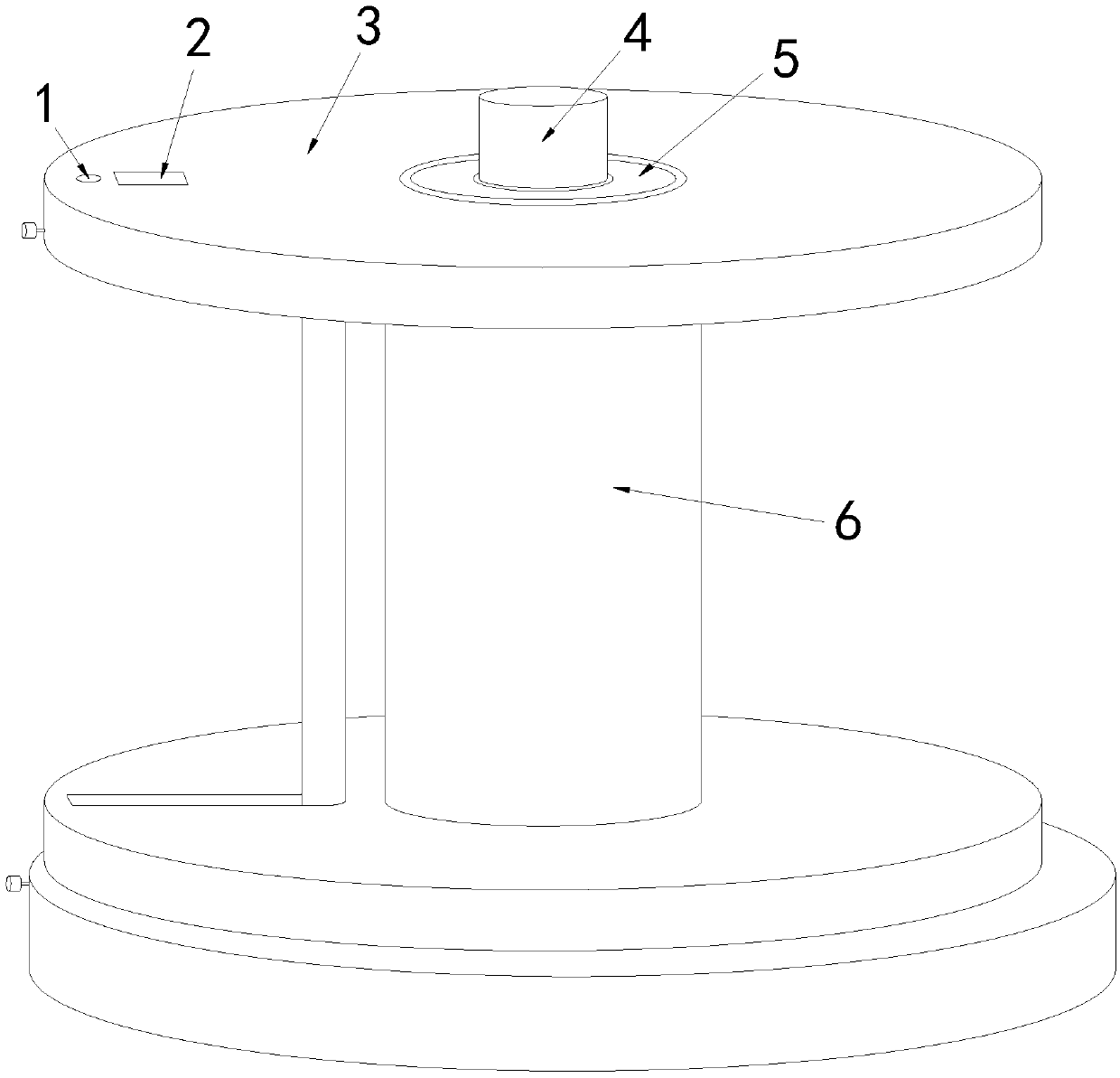
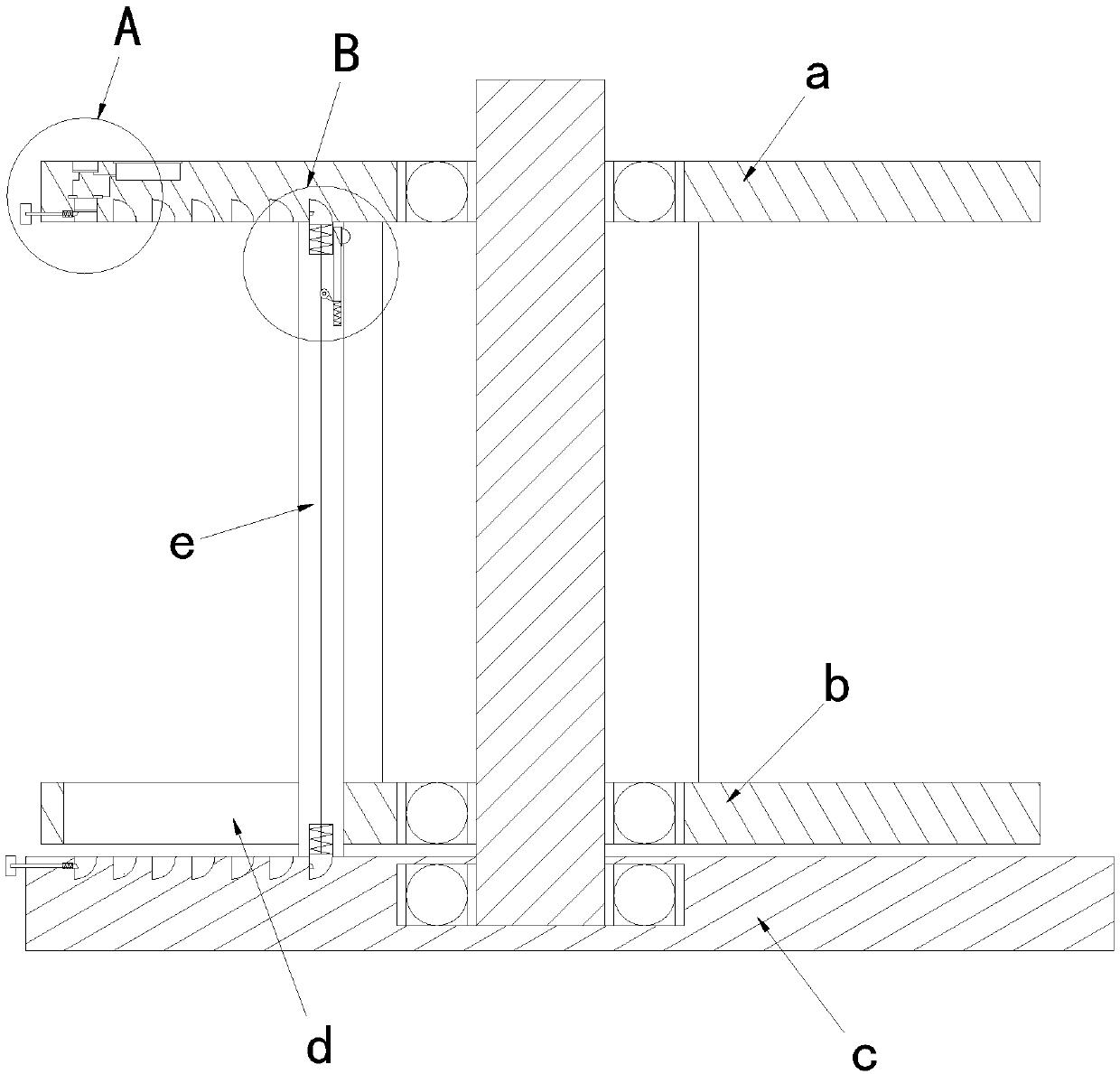
[0018] see Figure 1-Figure 4 , the present invention provides a technical scheme of a cable retractable carousel with automatic winding function: its structure includes a prompt horn 1, a battery 2, a coil limit device 3, a shaft 4, a bearing 5, and a retractable roller 6. The middle part of the coil wire limiting device 3 is inlaid and fastened with the shaft 4 through the bearing 5, and the retractable roller 6 is coated and welded on the middle part of the shaft rod 4 and embedded on the upper side of the coil wire limiting device 3. The left side of the top of the wire limit device 3 is inlaid with a prompt horn 1 and is electrically connected to the prompt horn 1. The battery 2 is inlaid and locked on the top of the coil limit device 3 and i...


PUM


Abstract

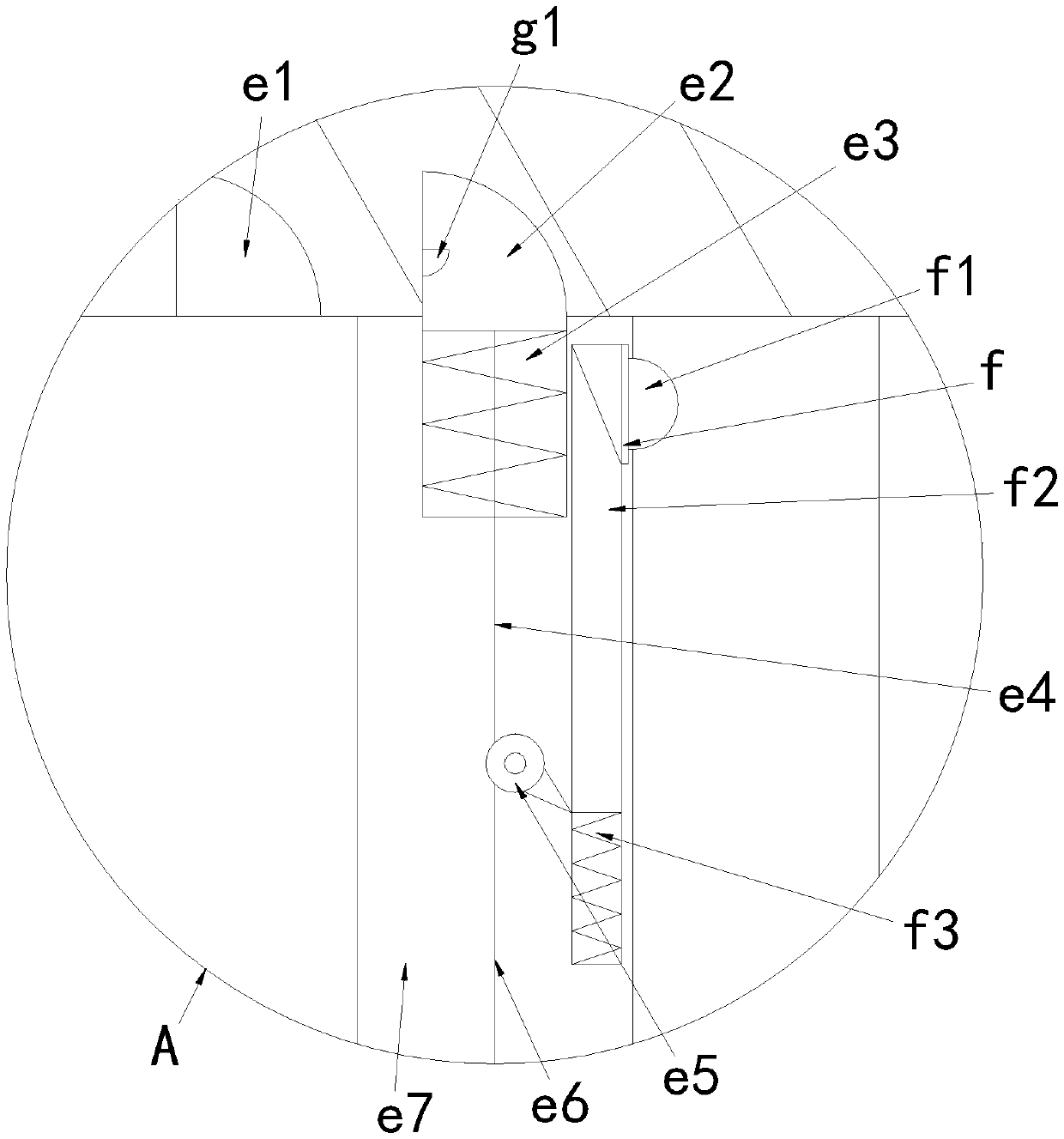
The invention discloses a cable winding and unwinding rotation disc with an automatic surrounding wire tidying function. The cable winding and unwinding rotation disc structurally comprises a prompt horn, a battery, a wire coiling limiting device, a shaft rod, a bearing and a winding and unwinding roller. The shaft rod is embedded in the middle portion of the wire coiling limiting device in a buckle joint manner through the bearing. The winding and unwinding roller wraps and is welded to the middle portion of the shaft rod and is embedded and arranged in the middle upper side of the wire coiling limiting device. The left side of the top end of the wire coiling limiting device is in glue joint with the prompt horn in an embedded manner and electrically connected with the prompt horn. When the cable winding and unwinding rotation disc is used, through extrusion of an arranged wire tidying rod, a cable wire is sequentially coiled in a staged manner, accordingly, when the cable is unwoundafter being coiled, winding and knotting can be better prevented, and usage is convenient; and secondly, after the cable is coiled to a certain degree, the wire tidying rod can be locked and jacks andconducts a circuit of the prompt horn, after full equipment winding, prompt can be conducted, the coiled wire is locked, the situation that coiling collapses due to excessive coiling, and consequently equipment pulling damage is caused is prevented, the equipment safety is guaranteed, and usage is convenient.

Description

technical field [0001] The invention relates to a cable retractable turntable with the function of automatically wrapping and arranging cables, belonging to the field of cable retractable turntables. Background technique [0002] Cable retractable turntable, when the cable is used and retracted, due to the heavy weight of the cable itself, manual winding is not easy, so it is often necessary to use a disc-shaped wire roller to coil, which is the cable retractable turntable. [0003] When the traditional cable take-up turntable is in use, the automatic take-up cannot perform the winding of the cable according to the order of the inner and outer rings, resulting in 1. It is easy to cause the cable to be coiled at the bottom due to the weight of the cable when it is coiled, which is easy to cause the cable to be coiled in the follow-up. It is entangled and knotted when taken out, causing inconvenience when unwinding; 2. The cable is easy to coil over the limit and cause the cab...

Claims


Application Information

Patent Timeline
IPC IPC(8): B65H75/14B65H75/18B65H75/28
CPCB65H75/14B65H75/18B65H75/285B65H2701/34
Inventor 李姗姗
Owner 安徽东明电气有限公司
Learn More